A few minutes ago an advertisement killed my posting.
I strongly ask the mods to think about the concept of advertising.
Often it happens, when I klick on attachments of postings that another window/tab opens and forces me to shop web pages etc.
My reaction is not at all that I would buy things there, it is more that I blacklist these companies.
Today it was worse. When sending my post - an advertisement page popped up.
I closed it, at least I intended to close it, but instead of getting rid of that advertisement my posting was killed. I do not care whether I might have missed the closing button by 1mm, but this sort of advertising is unacceptable to me!
Unfortunately I cannot do much more than blacklisting also this company....
I learned to live with floods of advertisement, but this newer sort of harassment and duress is really killing the fun on DIYaudio.
The over voltage protection is still an open topic.
Desireable shut down window: 92V...100V
OVP1
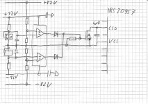
My high end proposal with a dual OP and two precision references would end up
in the following additional components and solder joints for the OVP:
17 components
43 solder joints
Precision OK.
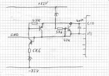
OVP2
Pergo's proposal with zener diodes:
9 components
21 solder joints
Tolerances and thermal drift of zeners, availability of the right zeners and the soft+slow discharging
of the 4u7 will make it hard to hit a reasonable shut down window.
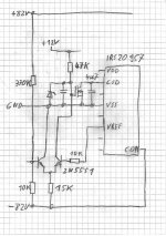
OVP3
Another approach:
It is not necessary to check both rails in seperate, but the sum is relevant.
Furtheron the IRS20957 has a reference on board.
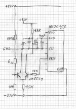
By measuring VREF and the real values of 330k and 10k it is easy to calculate the
necessary Rx. Of course for mass production such approach is unpleasant, but for DIY it is easy.
Both 2N5551 should be glued together in order to keep thermal errors acceptable.
11 components
25 solder joints
Precision: Adjustment needed.
Votes?
Further proposals?
If yes, please prepare in a comparable way.
Desireable shut down window: 92V...100V
OVP1
My high end proposal with a dual OP and two precision references would end up
in the following additional components and solder joints for the OVP:
17 components
43 solder joints
Precision OK.
OVP2
Pergo's proposal with zener diodes:
9 components
21 solder joints
Tolerances and thermal drift of zeners, availability of the right zeners and the soft+slow discharging
of the 4u7 will make it hard to hit a reasonable shut down window.
OVP3
Another approach:
It is not necessary to check both rails in seperate, but the sum is relevant.
Furtheron the IRS20957 has a reference on board.
By measuring VREF and the real values of 330k and 10k it is easy to calculate the
necessary Rx. Of course for mass production such approach is unpleasant, but for DIY it is easy.
Both 2N5551 should be glued together in order to keep thermal errors acceptable.
11 components
25 solder joints
Precision: Adjustment needed.
Votes?
Further proposals?
If yes, please prepare in a comparable way.
Attachments
Last edited:
Better accuracy?
You mean better burning! It is not likely that a small zener and the base-emitter path can handle the currents that you would get by this clamping of the high power PSU.
I think it will need the series resistor.
Please note that this shut down disables the class D amp,
but supply voltage can still increase.
Depending on the used PSU, there might be the option to shut down the PSU as well, but some folks might even use a monster transformer with rectifier and caps....
The shut down has to be set below a sum of 200V, definitely yes.
In case of good snubbering you do not need excessive margin there.
Setting it to 185V...190V should be OK.
For experiments with the intended choke for SystemD_2kW, I used SystemD_MD, which uses 150V-MosFets and ran this amp with +/-74V rails for pretty some time (first thermal considerations for the intended 2kW choke...). The amp acted like this would be normal. At room temperature typically the real avalanche happens not earlier than 10% above the specified voltage rating. Furtheron the avalanche voltage slightly increases with temperature and last but not least some amount of avalanche energy is allowed without destruction.
I think stopping the IRS should cover even serious overvoltage as long as the 100V rail caps do not lift their heads.
Closer look: As soon as the IRS stops, the output will be pulled towards GND by the feedback resistor and/or speaker. With this the Mosfets and the IRS will not see the full voltage any more but just the difference between rail and output.
An upgrade with much more comparator gain could be the second schematic, still I am not convinced that the extra efforts are worth it. But it simulates nice. Sloping with the concerned input signals takes 30ns, delay just a few ns (hard to believe).
Please also note the inspiration from Workhorse combined with my improvement to move the mirror to a neg voltage and clamping which avoids saturation of the BJTs.
Nice improvement Choco,
Clamping them with low reverse current schottky's will add further to improvement.
For the impatient ones:
If driven to around 10% of max output voltage the influence on THD (which is low in this situation anyway) is benign, at 90% drive it means a THD improvement of about tenfold. But these are simulations and have to be taken with the usual grain of salt of course.
Regards
Charles
Hi Master,
I shall assume by 90% drive you mean during the large signal response[close to high voltage output swing near/close to rails] the hysteresis control is most worthy of its implementation. If this is the case then i think its good to explore more into this. Simulation looks extremely promising.

regards,
Kanwar
I shall assume by 90% drive you mean during the large signal response[close to high voltage output swing near/close to rails] the hysteresis control is most worthy of its implementation.
Yes, exactly. Because this isn't my mother-tongue I sometimes express myself in a little (?) unclear way.
It is also a problem with carrier-based amps that distortion increases with drive due to carrier aliasing (other factors conme into play as well but this is an often diregarded one). Some principles used to fight it are the carrier pre-distortion proposed by Candy or the MAE loops used by TI.
Regards
Charles
I did some search for dynamic hysteresis control in class-d amps. There are some papers around one for which would have to pay for, for instance from IEEE.
But here are some interesting ones that are freely available:
This one is from ADI and is dealing with delta-sigma converters. From page 84 they explain their implementation of dynamic hysteresis into their range of delta-sigma based class-d amplifiers.
http://www.cscamm.umd.edu/programs/ocq05/adams/adams_ocq05.pdf
This one here is a patent by Toshiba which comes quite close to our proposals. Although the technical implementation is different to our proposals the general idea is quite close. From the legal perspective the claims would have to be analysed in detail in order to be sure. The modulation of the frequency is done via a transconductance amplifier. The patent also shows a way to implement dither to reduce EMI problems. But they don't use post filter NFB. The patent fees are due this year. Maybe they refrain from paying because of lack of interest and the patent will cease.
Espacenet - Bibliographic data
Regards
Charles
Few more not so similar links
http://orbit.dtu.dk/fedora/objects/orbit:19614/datastreams/file_4386094/content
http://www.elkraft.ntnu.no/norpie/10956873/Final Papers/029.pdf
Class-D amplifier with enhanced bandwidth
http://kweb.no-ip.org/jw/mediaplayer-5.6/data/ic/CDA/CDROM/Thesis_electronic_file/thesis.pdf
http://orbit.dtu.dk/fedora/objects/orbit:19614/datastreams/file_4386094/content
http://www.elkraft.ntnu.no/norpie/10956873/Final Papers/029.pdf
Class-D amplifier with enhanced bandwidth
http://kweb.no-ip.org/jw/mediaplayer-5.6/data/ic/CDA/CDROM/Thesis_electronic_file/thesis.pdf
I think gain controllable OTAs offer exactly the functionality (2 quadrant multiplier), which help to ease Charles' approach.
LM13600/13700 could be worth a trial.
Critical point would be the bandwidth of 2MHz, which might not reproduce a 400kHz rectangle in a sufficient way way.
Noise of the LM13600 should not be an issue because it would be inside the feedback loop, from my understanding.
LM13600/13700 could be worth a trial.
Critical point would be the bandwidth of 2MHz, which might not reproduce a 400kHz rectangle in a sufficient way way.
Noise of the LM13600 should not be an issue because it would be inside the feedback loop, from my understanding.
Something DIY would probably kill an LM13600 performance-wise. Keep in mind that we actually only have to modulate a rectangular signal in Amplitude (no sinusoidal or the like). Therefore it should be possible to turn a positive and a negative current mirror (or some other controllable current-source) on and off.
Regards
Charles
Regards
Charles
Last edited:
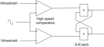
I wonder if you could use a window comparator, followed by an S-R latch as the modulator instead of a single comparator with hysteresis? I used the same arrangement in the past where I wanted variable hysteresis without all of the tolerance issues that setting an accurate hysteresis level involves. You have to provide symetrical threshold voltages to the window comparator to set the (emulated) hysteresis effect, but that shouldn't be too difficult, although very high speed op-amps would be required to follow the switching waveform. A hastily drawn Visio pic is attached.
Attachments
Very nice and even simpler than the idea that I just had. And even more embarassing for me .....
My new idea was a mixture of the one that I presented and Markus' clamping idea. Now I wonder if it still makes sense to present it.
BTW: No need for very high speed OP-AMPs because they would not have to handle the switching signal. They are used to generate the hysteresis level as a function of the audio signal. They would not even have to offer low THD or low noise.
Regards
Charles
Last edited:
...absolutely great. I love your contributions!
Regarding the build itself I am tending to the simple solution of posting #3,
because it seems to serve the needs (==> low HF ripple and 15db improved THD at 90%) and at the same time makes Mr. Nitpicker happy:
18 components
40 solder joints
But besides this 'low brainer comment' let's go on with the discussion
Another idea just popped up which is quite simple. The most annoying part of it is the fact that it didn't pop up earlier. I'll post info as soon as I have "tried" it out.
Regards
Charles
An option for Mr. Nitpicker?
- Home
- Amplifiers
- Class D
- SystemD_2kW, any interest for an open design?