If, in fact, the tests done by TMM are valid and the problems and noise are centered around the Korean made clone TA2020, then what would be the point in buying a "properly made and laid out TA2020 amp" when they will have the same Korean made clone TA2020?
Welll.. IMO the Korean clones were likely the good ones
")
One would be genuinely Lucky to receive one of those.
It's the far cheaper copies 'Fabrique En Chine' that masquerade as Korean Made.. that are the crux of the problem.
But then half the parts on the PCB's are copies of copies as well.
Hello all, this is my first post but I have been reading and following the forum for a while and have learned a lot so first let me thank everyone for all I have learned.
I am in the have the 2020A+ (actually a copy but the only change I can see is 2 relays rather than 1) and have been modding it for a while largely using what I have learned here.
I have read that replacing the output inductors will improve quality a bit. Do you feel this is worth the cost/effort and if so what are the tolerances on replacements as I am unable to find ones with the same rating.
Thanks again
I have read that
quality post
Thanks for the measurement. This amp has BTL output, did you measure it differentially or just single end output. For the even order harmonic distortion, measure it differetially, you can get different result from measure it single-endedly.
I measured TA2024 chip amplifier before, single endedly, the result is not good, especially with dummy load. But that is before I change the output inductors, which make sounds as the music you play(source of extra nonlinearity).
This thread needs less subjective opinions about capacitors and more objectivity, so i will add my 2c.
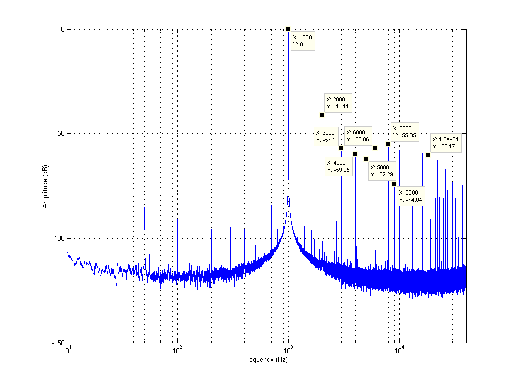
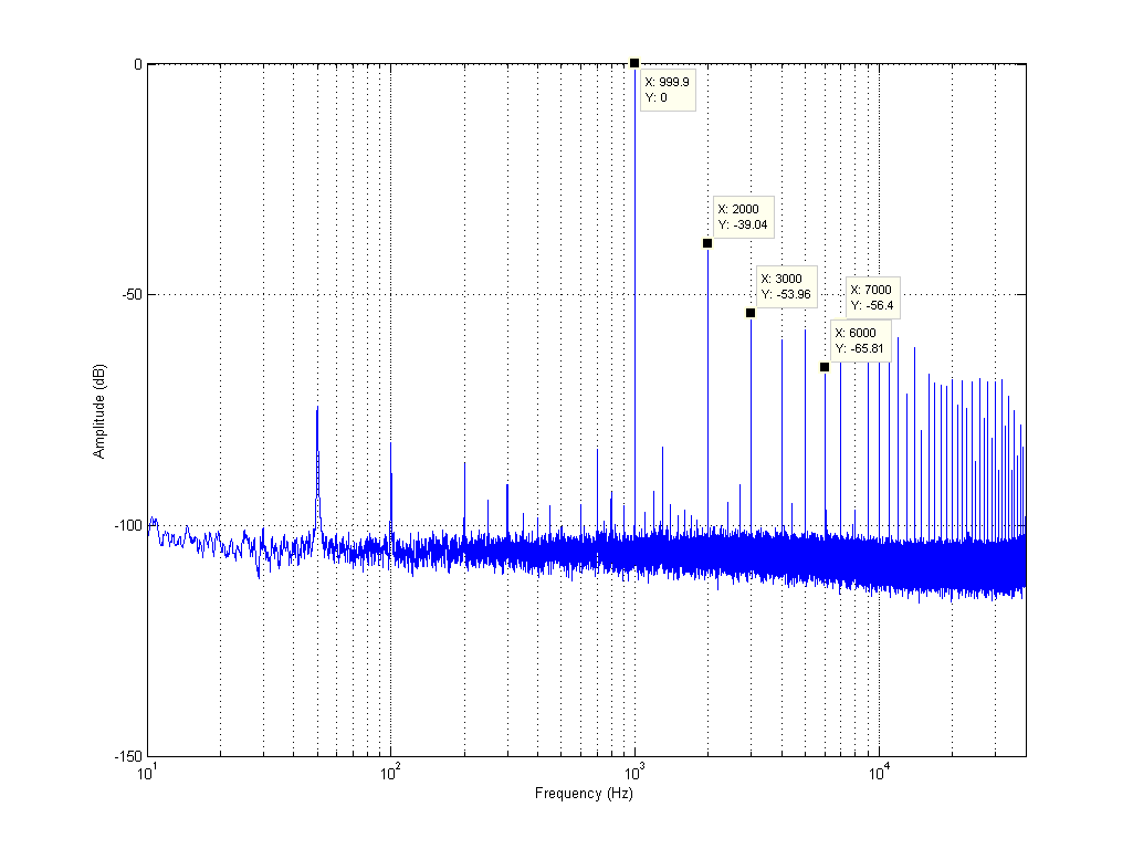
Measured my 2020A+, completely stock:
1W @ 8ohm, 1khz test tone:

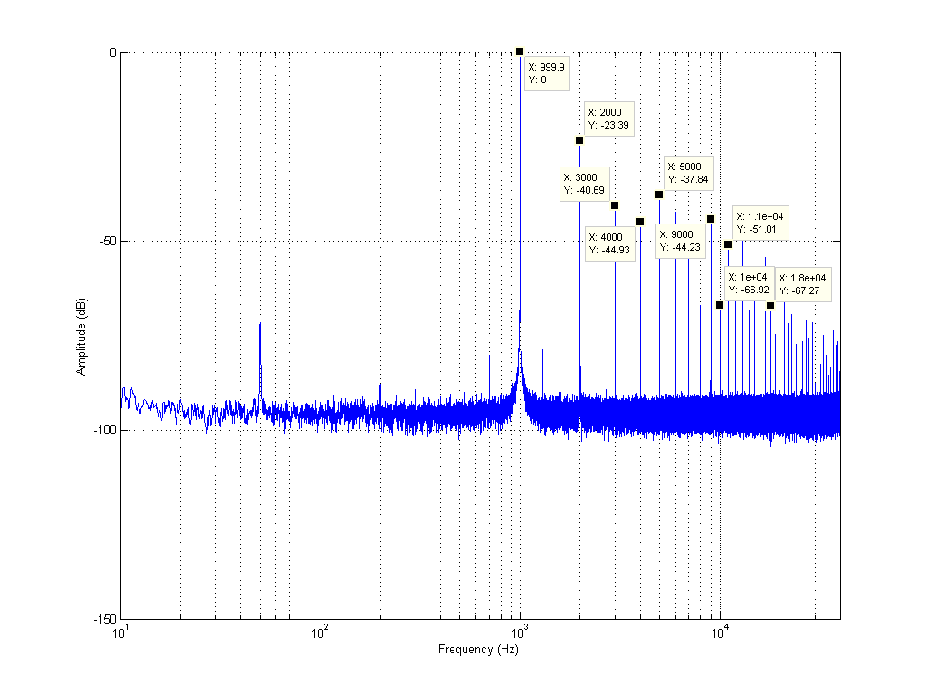
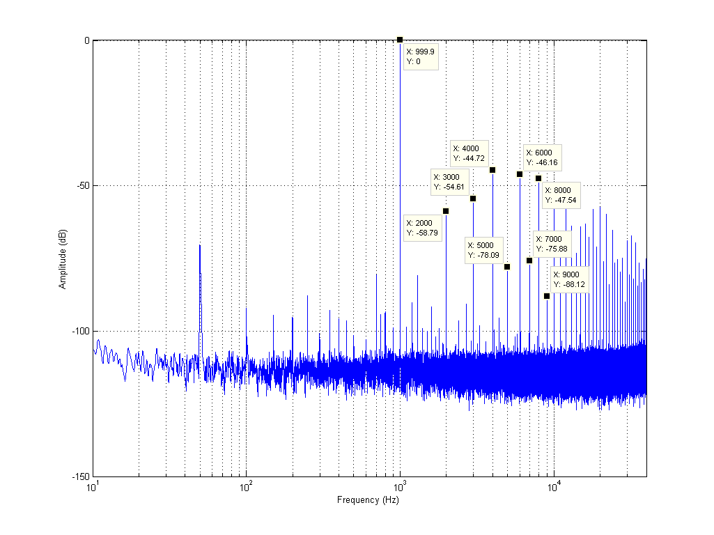
4.3W @ 8ohm (near max power):
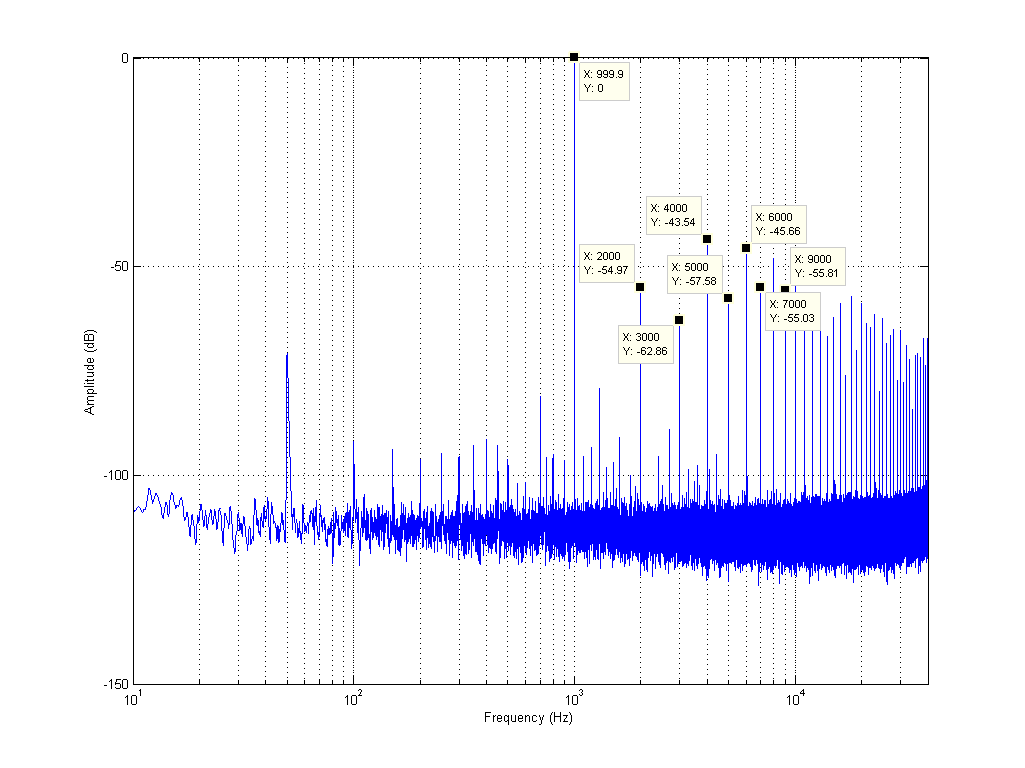
0.1W @ 8ohm:
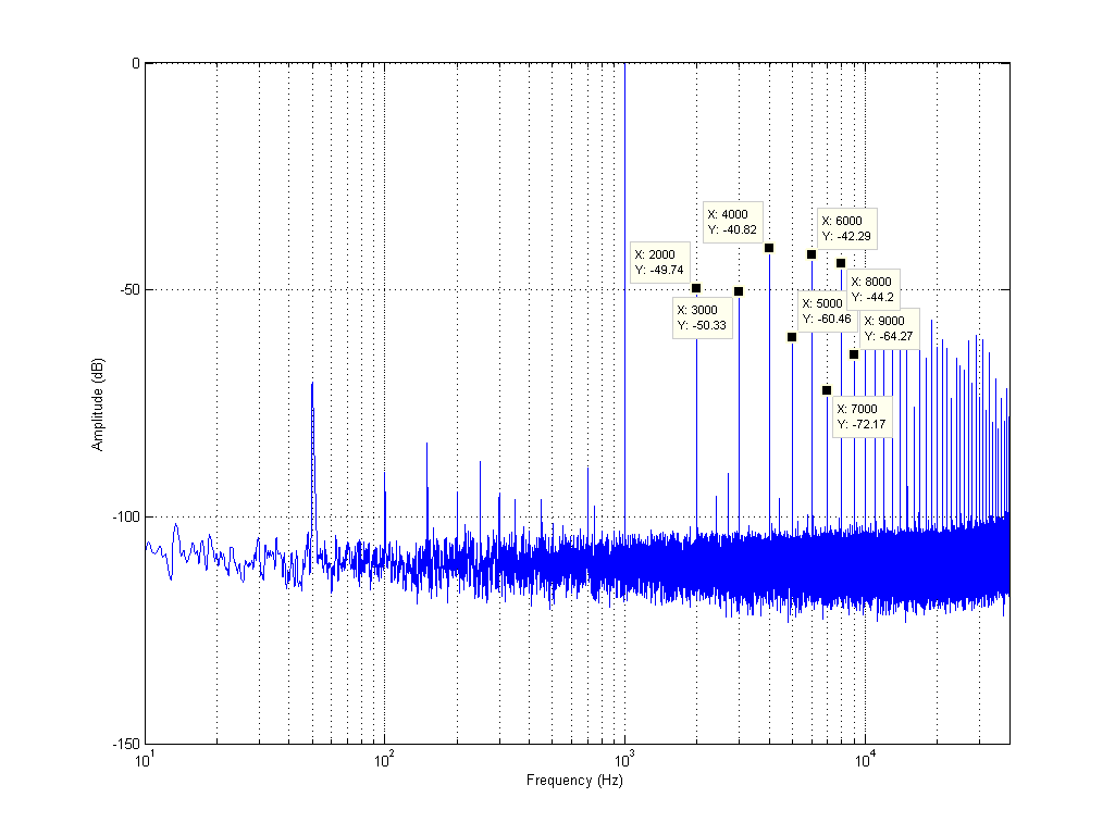
1W @ 4ohm (not sure what the hell is going on with the noise floor here!):
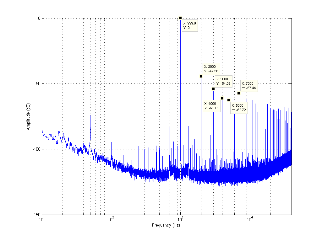
Oh dear, this is pretty awful distortion, especially at lower power levels (the most important ones!) and looks exactly the same as the Muse TA2024 amp i have. Distortion is okay i guess (except 2nd order) near max power, but since music is dynamic this is pretty moot. You can't play music at 4.3W without playing 0.1W simultaneously. It will however be much better playing loudly than quietly.
Anyone who has played with and measured speaker amplifiers and opamps will know that the level of distortion above is unlikely to be caused by the simple opamp circuits. Also the similarity to the Muse TA2024 amp (which has no preamp or tone control circuitry what so ever) immediately makes me suspect that the distortion is being produced entirely by the TA2020 chip.
Even at max power, i wasn't achieving anywhere near the quoted total harmonic distortion figure in the TA2020 datasheet which is 0.03% @ 10W 4ohm. 0.03% corresponds to -70dB, and i had single harmonics that measured higher than that! On 12v the best my chip can muster without clipping is 5Vrms @ 4ohm = (5^2)/4=6.25Watt and 6.3Vrms @ 8ohm = (6.3^2)/8=5Watt. My Muse TA2024 amp is similar. So we probably need a 13.5v supply to get rated power output, but you'd think it would still get close to the quoted 0.03% distortion.
I had a brainwave that maybe BOTH outputs need to be loaded up to achieve low distortion. So lets try that. Max power with both channels loaded with 4ohm resistors.
Nope. The general trend is that total harmonic distortion gets lower as power output increases - except 2nd order, which just gets worse as you crank up the juice (but also bad at very low power levels).
The first mod i tried was lowering the gain. Default value of Rf on my board is 22k, and Ri is 15k. According to the 2020 datasheet that gives us a gain of 12*(22/15)=17.6.
I soldered 20K resistors across pins 9 and 10, 12 and 13 of the 2020 chip. This lowers the gain to 12*(10.48/15)=8.4
Here are the results of that:
Odd order distortion goes down significantly, but even order seems to be relatively unchanged.
The next thing i tried was to replace the output inductors. I wound some 10uH aircores with 20AWG wire:
3rd order comes down, 5th, 7th and 9th go up! Why the heck did that happen? More on this later...
Then i tried some of the 'usual' mods in this thread. First i cut the trace between R18, R19 and the volume pot, therefore completely isolating the tone control circuit at both the input and output. I measured, and there was absolutely no change.
Then i removed one of the 2.2uf decoupling caps and connected my input signal directly to the input of the 2020 chip via a 560nF polypropylene cap. No change.
At this point i was getting frustrated as to why my measurements weren't repeatable. I'd go and change the gain resistor to another value, then change it back to 20k and get a worse result than when i first measured it with the 20k resistor.
Maybe heat is affecting it? First i sprayed the heatsink with freeze spray:
Then heated it up:

This may also go some ways as to explain why the distortion gets lower at higher power outputs.
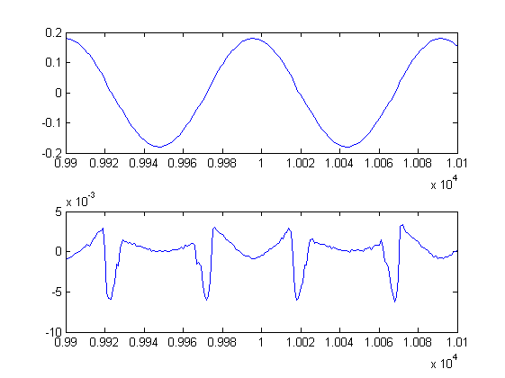
If we look at the waveform with the 1khz tone notched out, we can see that the distortion mechanism is completely changing with temperature (output signal on top, notched signal below):
Room temp:
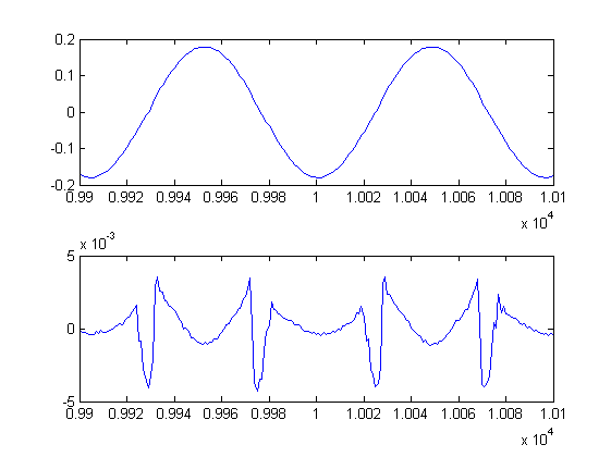
Cold:
Hot:
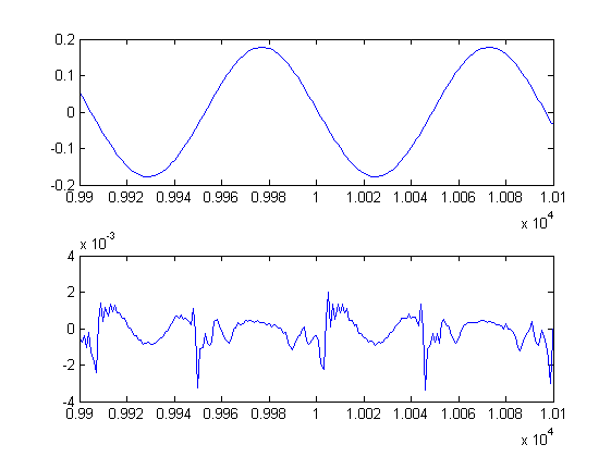
This in my eyes proves that the TA2020 chip itself is internally producing all of the distortion at the output and there is not much you can do to fix it. Reducing the gain is a worthwhile mod, but don't expect miracles. Running the chip hotter generally improves even-order distortion and running it cool improves odd-order. The happy medium seems to be the temperature it reaches at after running it at max power for several minutes (perhaps 45C?). Music won't let it get that hot (unless you severely clip the amp) so installing a smaller heatsink may actually improve performance in practice!
I haven't tested the amp with the tone controls enabled, but certainly there are no ill affects (at least amoungst the massive distortion caused by the 2020) in leaving it connected, plus it is generally nicer to have the knobs on the front of the unit actually do something (even if you never use them), rather than pointlessly disabling/removing them for no benefit.
I'm still yet to change any caps but having isolated all of them except the powersupply and output capacitors, and already using a decent regulated powersupply to power it, i'm going to predict that replacing the caps will be about as effective as pi**ing on a bushfire.
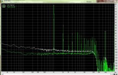
My test result
This is a MUSE amplifier with TA2024 chipset, with one modification is that it is powered with 12V 2A switching power supply buffered by a Capacitor multiplier(modified by myself), with an impedance under 40m Ohm from 20 to 20kHz.
It looks better, tested at level right before clipping. one channel with 8Ohm load, the other is without load. single-ended test results.
Attachments
Last edited:
Hello everyone,
Finally i'm join here now, i got my Lepai for about 3 weeks and i have mod it as i see here, bypassing tone control, change all thru hole caps with Panasonic, Caps input with Bennic, and it really worth for it cost...
Finally i'm join here now, i got my Lepai for about 3 weeks and i have mod it as i see here, bypassing tone control, change all thru hole caps with Panasonic, Caps input with Bennic, and it really worth for it cost...
An externally hosted image should be here but it was not working when we last tested it.
An externally hosted image should be here but it was not working when we last tested it.
An externally hosted image should be here but it was not working when we last tested it.
Last edited:
Hey guys new here, I just ordered the upgraded output caps, and 5600uF low esr input cap from mouser as reconmended by "XtremeRevolution" at Parts Express forums. While I was following the post he mentions that there are 3 holes that you can solder the output caps to and that we should use the outer holes as the new replacement caps are of a larger size. I looked over my board and notice that I have two relays instead of one so I don't have a 3rd hole on the two bottom output caps. Has anyone done this upgrade with a board like this? Is it OK to squeeze the legs of the capacitor together to fit in there?
I just noticed I have a LEPY model, do they spell it different all the time?
An externally hosted image should be here but it was not working when we last tested it.
I just noticed I have a LEPY model, do they spell it different all the time?
Hey guys new here, I just ordered the upgraded output caps, and 5600uF low esr input cap from mouser as reconmended by "XtremeRevolution" at Parts Express forums. While I was following the post he mentions that there are 3 holes that you can solder the output caps to and that we should use the outer holes as the new replacement caps are of a larger size. I looked over my board and notice that I have two relays instead of one so I don't have a 3rd hole on the two bottom output caps. Has anyone done this upgrade with a board like this? Is it OK to squeeze the legs of the capacitor together to fit in there?
It's perfectly fine to squeeze the leads together. Just try to get the cap leads as far into the board as possible, to reduce the "wire" length".
is there any guides to doing any of the suggested mods? that has like a parts list also?
Guess what
DIYAudio has a Lepai WIKIAmplifier:Lepai T Amp - diyAudio
Yes, this will be interesting to know how to make. I too want to keep the controls and swapping the OPAMPs with better ones. A couple of questions more:
1. I see some of you guys decided to change the small caps C34, C37 (near the Inductors). I see in the datasheet of TA2020 the value is 0.1uF (100nF), but in several posts I see 0.01uF ? Is this a mistake or there is some reason? I can buy WIMA polyester of both values, so please advise.
2. Another question regarding the Zobel Network - what is the reason to change the 10 ohm resistors with 6.8 ohm and the related change in C35, C39 with 0.22uF? I have 4 ohm speakers and don't know if that change is applicable for me, or to stay with default values (10 ohm, 0.47uF). I have 0.6W resistors of both types.
3. Some posts are dealing with the Zener diode D2. Is safe to remove it when adding the additional Schottkys? I should replace with direct wire bridge in this case?
I have Microlab SOLO 7 speakers converted to passive (the embedded Amp died). They are 4 ohm and probably suitable for the Amp. If there are other recommendations please, advise. I will swap the other caps too with Low ESR ones, the power supply is 12V 6A.
So I want to share with you guys how I swapped the parts of this little AMP. It finally arrived and is built with very cheap parts, actually it's a crap low quality peace. I directly swapped almost everything and it now sounds beautiful
Here is the part list:
Audio input smd caps C30 C31 near the input RCAs and the audio input caps to Tripath chip C20 C21 - replaced with Wima 2.2uF 63V 10% MKS2
All electrolytic caps replaced with Low ESR ones - I have here only Taiwanese HITANO Low ESRs so no other choice for me. The main power filter C1 was replaced with 4700uF one and additional ceramic cap 220nF 50V X7R P5 added at the bottom side of the PCB. The values of the other electrolytics are kept like the original.
The power input choke L1 was swapped with Panasonic 3.3UH, 0.016OHM, 5.2A.
The audio output chokes L2 L3 L4 L5 - swapped with Panasonics ELC10D100E 10UH, 3.9A, 0R026
Audio output caps C32 C33 C36 C38 swapped with Wima 470nF 63V 10% MKS2
These two changes are according the datasheet of Tripath:
Audio output caps C35 C39 swapped with Wima 220nF 63V 10% MKS2
Audio output resistors R38 R39 - swapped with 10 Ohm 1/2W
It seems the board was purely designed with equal caps in the output section but I decided to follow the datasheet for 4 Ohm speakers
I replaced too the two smd caps C34 C37 with Wima 10nF 63V 10% MKS02 which I placed underneath the PCB (it was easier for me)
C9 replaced with Panasonic ECW-F2W104JAQ .1µF 450V
Finally I decided to try the AMP with the default OP AMPs after all these changes - it sounds beautiful with my Microlabs SOLO7s converted to passive I was surprised how nice and powerful it was and with clean sound. The audio feed is from Asus Xonar DX, the power source is 12V 6.5A power supply brick for LEDs. For now the AMP is good enough for me and I left the OP AMPs unchanged. However the mentioned problem with power On/Off popping sound is present. If someone has a solution to that, please share it with us.
Here is the part list:
Audio input smd caps C30 C31 near the input RCAs and the audio input caps to Tripath chip C20 C21 - replaced with Wima 2.2uF 63V 10% MKS2
All electrolytic caps replaced with Low ESR ones - I have here only Taiwanese HITANO Low ESRs so no other choice for me. The main power filter C1 was replaced with 4700uF one and additional ceramic cap 220nF 50V X7R P5 added at the bottom side of the PCB. The values of the other electrolytics are kept like the original.
The power input choke L1 was swapped with Panasonic 3.3UH, 0.016OHM, 5.2A.
The audio output chokes L2 L3 L4 L5 - swapped with Panasonics ELC10D100E 10UH, 3.9A, 0R026
Audio output caps C32 C33 C36 C38 swapped with Wima 470nF 63V 10% MKS2
These two changes are according the datasheet of Tripath:
Audio output caps C35 C39 swapped with Wima 220nF 63V 10% MKS2
Audio output resistors R38 R39 - swapped with 10 Ohm 1/2W
It seems the board was purely designed with equal caps in the output section but I decided to follow the datasheet for 4 Ohm speakers
I replaced too the two smd caps C34 C37 with Wima 10nF 63V 10% MKS02 which I placed underneath the PCB (it was easier for me)
C9 replaced with Panasonic ECW-F2W104JAQ .1µF 450V
Finally I decided to try the AMP with the default OP AMPs after all these changes - it sounds beautiful with my Microlabs SOLO7s converted to passive
I was surprised how nice and powerful it was and with clean sound. The audio feed is from Asus Xonar DX, the power source is 12V 6.5A power supply brick for LEDs. For now the AMP is good enough for me and I left the OP AMPs unchanged. However the mentioned problem with power On/Off popping sound is present. If someone has a solution to that, please share it with us.another set of LP-2020A+ mods
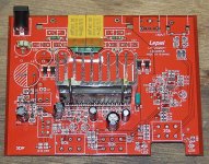
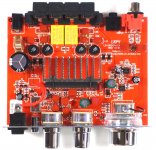
I needed a small amplifier and ended up purchasing a Lepai LP-2020A+ 20W unit for US$21. At first listening I was not impressed so decided to incorporate some of the suggestions from this forum as well as those on the Parts Express web page.
The board in my unit was marked Lepy LP-2020A+ 131005PCB. This is a more recent version than some of the boards in earlier discussions. I concentrated on the input op amps and the signal-coupling capacitors. In addition I replaced the output inductors. I'm not sure how much of a change the inductors made but at least I now know the specs on the parts. Finally, I updated some of the supply decoupling capacitors. I also added some 0.1 uF chip caps on the bottom of the board between the leads of all the decoupling electrolytic caps. At audio frequencies I don't think this makes much of a difference but I had the parts in the junk box so decided to use them.
A photo of the modified board is attached. The sound from the amp is significantly better and meets my needs. I'm quite happy with the $17 investment in the upgrade parts.
The parts list with Digi-Key part numbers follows -
(2) 497-10230-1-ND
STMicroelectronics TL082BIYDT IC OPAMP JFET 4MHZ 8SO
U1, U2
(4) 732-3747-ND
Wurth Electronics Inc 744732100 INDUCTOR 10UH 4A 8075 RAD
replaces old inductors which are 0.026 ohm, new are 0.023 ohm
L2, L3, L4, L5
(1) 565-1065-ND
United Chemi-Con CAP ALUM 3300UF 25V 20% RADIAL
replaces 2200uF 16V 85C
C1
(10) P4675-ND
Panasonic CAP FILM 1UF 50VDC RADIAL
replaces 1uF 50V 105C
C4, C10
two stacked bottom-to-bottom replaces 3.3uF 50V 105C NP
C20, C21
two stacked side-to-side replaces chip caps ~2uF
C30, C31
Hello i have one problem.. so i think i broke volume potentiometer on my lepai so i would like to bypass it (remove) so you can only change volume on source device.. how its possible?
Do i need to connect it with wire like this: Screenshot by Lightshot ??
Please fast reply thanks
Do i need to connect it with wire like this: Screenshot by Lightshot ??
Please fast reply thanks
Any wire will do; it doesn't need to be anything special. Just use it to jumper from the input side of the potentiometer circuit to the wiper side of the potentiometer circuit. And cut the old PC trace that runs to the pot input. I wouldn't fuss with removing the volume pot.
Hi, I sometimes run my lepai from a 12v lead acid battery. Unfortunately when it's fully charged the voltage is sometimes too high and the amp won't work. I'm thinking that I need a low dropout voltage regulator, but I'm not an electronics engineer...
http://m.rs-online.com/h5/mobile/uk/catalog?url=/web/p/low-dropout-voltage-regulators/5339381/
Am I on the right tracks? Has anyone solved this problem? Thanks in advance!
http://m.rs-online.com/h5/mobile/uk/catalog?url=/web/p/low-dropout-voltage-regulators/5339381/
Am I on the right tracks? Has anyone solved this problem? Thanks in advance!
- Status
- This old topic is closed. If you want to reopen this topic, contact a moderator using the "Report Post" button.
- Home
- Amplifiers
- Class D
- LP-2020A+ mod thread