Wow. That's insane. You might need a bigger case... Maybe. ")
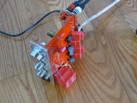
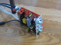
Here's pictures of my caps, "temporary placement"
Awaiting virpz's definitive mod post, so I can decide where to fit everything..
In this case I can avoid removing any component but C20 and C21?
Is that right?
Pretty much. You'll have to remove C30, C31 and run the caps from the top pads of those to the right hand side of C20, C21 (if you plan on using the built in inputs).
Here is my plan to use the Lepai as a final stage with and without DC blocker.
First of all I will play with the Lepai volume control to find the correct input impedance (R) that optimizes the pre-lepai coupling.
Remove all caps, opamps and pots (volume, bass and treble) on the left side of the pot (see schematic).
Remove C20 and C21 and shorten tracks (in the output stage of my pre I have already two paper-in-oil 2uF caps).
Connect the inputs directly to pin # 1 of the switch.
Connect the inputs directly to pin # 3 of the switch through a 2uF film cap (I do already have a couple of clarity caps).
In this way I can use the tone/direct switch for excluding the DC blocker.
Here is my plan to use the Lepai as a final stage with and without DC blocker.
First of all I will play with the Lepai volume control to find the correct input impedance (R) that optimizes the pre-lepai coupling.
Remove all caps, opamps and pots (volume, bass and treble) on the left side of the pot (see schematic).
Remove C20 and C21 and shorten tracks (in the output stage of my pre I have already two paper-in-oil 2uF caps).
Connect the inputs directly to pin # 1 of the switch.
Connect the inputs directly to pin # 3 of the switch through a 2uF film cap (I do already have a couple of clarity caps).
In this way I can use the tone/direct switch for excluding the DC blocker.
Hey fuki, why do you want to do this?
just to test out between the "difference" of with/without dc block caps?
it'd be easier to just buy a second lepai if you want to compare, vs all the work that you'll put in just to "do this"

Hey fuki, why do you want to do this?
just to test out between the "difference" of with/without dc block caps?
it'd be easier to just buy a second lepai if you want to compare, vs all the work that you'll put in just to "do this"
I want to play that's all!cigar box amp
TP - Consider finding a really nice cigar box, big enough that you could fit your modded board into. Cut a rectangular opening in the front of the box and just screw the amp's faceplate to it to mount.
Like this guy does with the birchwood cabinets.
Modified Lepai T-Amplifier | nsmt loudspeakers
Here's pictures of my caps, "temporary placement" Honestly I don't think I can fit everything in the case...
TP - Consider finding a really nice cigar box, big enough that you could fit your modded board into. Cut a rectangular opening in the front of the box and just screw the amp's faceplate to it to mount.
Like this guy does with the birchwood cabinets.
Modified Lepai T-Amplifier | nsmt loudspeakers
Scratch built from Japan
Not a Lepai but an interesting page on building a TA2020 from scratch.
making Digial Amp -- TA2020-20 --
Near the bottom of the page the builder claims a difference in sound when he disconnects pin 30 (5v out) and connects pins 2 & 8 to an external 5v regulator. Take it with a gain of salt but if you like experimenting it's something else to play with.
Someone earlier asked about a tube preamp using the 6111WA tube. I found this (bottom of page): Quad Amplifier 4 You can find the kit on Ebay by searching 6111 preamp.
Got a pic of my homebrew of it here: http://www.diyaudio.com/forums/tubes-valves/173084-ge6111-preamplifier-5.html
TP - Consider finding a really nice cigar box, big enough that you could fit your modded board into. Cut a rectangular opening in the front of the box and just screw the amp's faceplate to it to mount.
Like this guy does with the birchwood cabinets.
Modified Lepai T-Amplifier | nsmt loudspeakers
That's a great idea!
Fried!
Something's gone fried:
Yesterday I made the mods but something has gone wrong.
I made the basic mods, removed the tone controls, the pot, capacitors and opamps.
I wired the inputs directly to the right side of C20 and C21 (as seen in pics).
I did short inputs and use a couple of 6ohm resistors output side.
After a while the resistors got very hot and then I measured about 12V DC at the outpus of the Lepai!
First question is:
1) Is the 2020A irremediabily gone?
2) What was wrong in my config? The only differences respect to original schematics is that I did not use any DC blocker as I'm sure that pre-amp has not any residual output DC.
On the first try indeed I took the input directly from the RCA plugs (see pic) and connected the Lepai to my pre instead of shortening inputs. Could this been dangerous for the Lepai?
Please help me!
TX
Last edited:
After a while the resistors got very hot and then I measured about 12V DC at the outpus of the Lepai!
The only differences respect to original schematics is that I did not use any DC blocker as I'm sure that pre-amp has not any residual output DC.
Measure your pre-amp, don't guess! Then multiply what you measure by 20 and that's about what your speakers will see.
Where did you measure the outputs with respect to? + to - or + to ground? This is a bridged amp with a single supply, there's probably +12V on + AND - with respect to ground, which gives 0V between + and -.
Unfortunately I measured 12V on + AND -.
I've ordered another Lepai: in case I want to remove the pot should I get the signal directly from the RCA inputs or between R37 and R34?
Last edited:
Unfortunately I measured 12V on + AND -.
I've ordered another Lepai: in case I want to remove the pot should I get the signal directly from the RCA inputs or between R37 and R34?
doesn't matter.. keep the decoupling caps to be safe I guess.
Unfortunately I measured 12V on + AND -.
I've ordered another Lepai: in case I want to remove the pot should I get the signal directly from the RCA inputs or between R37 and R34?
Do not go from between R37 and R34. Either go from the pads on C30/C31, or straight from the input jacks.
Unfortunately I measured 12V on + AND -.
I've ordered another Lepai: in case I want to remove the pot should I get the signal directly from the RCA inputs or between R37 and R34?
Take a Look at the datasheet, there is a fault pin, check the voltage there, to be sure that the chip its gone... If its gone... You always can order only the TA2020 IC, and change it... It Will be always cheaper than ordering a new lepai... Its what I did with My first lepai that blew cause I desoldered without discharging the input big cap... And now I have that one working with a total tone/volume components removed ... And its has a great sound...
Take a Look at the datasheet, there is a fault pin, check the voltage there, to be sure that the chip its gone... If its gone... You always can order only the TA2020 IC, and change it... It Will be always cheaper than ordering a new lepai... Its what I did with My first lepai that blew cause I desoldered without discharging the input big cap... And now I have that one working with a total tone/volume components removed ... And its has a great sound...
danzz I see on the data sheet that fault pin is #18 but which voltage should I expect to exclude possible failures?
Also can check pin 6 Which its the overloadb pin, you should have 5V in there as it says in the datasheet...From looking at the datasheet it says 5V for fault, and I would presume 0V for no fault.
Overload
The OVERLOADB pin is a 5V logic output. When low, it indicates that the level of the input signal has overloaded the amplifier resulting in increased distortion at the output. The OVERLOADB signal can be used to control a distortion indicator light or LED through a simple buffer circuit.
About the fault pin...
Fault Pin
The FAULT pin is a 5V logic output that indicates various fault conditions within the device. These conditions include: low supply voltage, low charge pump voltage, low 5V regulator voltage, over current at any output, and junction temperature greater than approximately 155°C. The FAULT output is capable of directly driving an LED through a series 2KΩ resistor. If the FAULT pin is connected directly to the MUTE input an automatic reset will occur in the event of an over-current condition.
TX. I will try tonight. In the meanwhile the new Lepai arrived.
How did u tested the amp after mods? Did you shortened the inputs and the outputs before wiring the amp to the speakers?
No, I directly conected the iPhone as a source and some little speakers I made with some Tang Band w3 665SC I made for this purpouses...
- Status
- This old topic is closed. If you want to reopen this topic, contact a moderator using the "Report Post" button.
- Home
- Amplifiers
- Class D
- LP-2020A+ mod thread