My opinion is Panasonic FR ") I don't buy "audio" capacitors. I go for high ripple current and low ESR. FR are like the goodness of FM and FC in one.
I don't buy "audio" capacitors. I go for high ripple current and low ESR. FR are like the goodness of FM and FC in one.
The power relay isn't really necessary once you've gotten the "pop" to lessen, but I've never felt like I need to remove them from circuits.
The ideal output capacitors (which I assume you're talking about with those values) depend on the speaker impedance you'll be using.
If you really are talking bypass capacitors, I often use between 10uF and 100uF, sometimes bypassed with 0.1uF. In the case of this amp, I stayed pretty close to the values they provided, just with much better caps.
I don't buy "audio" capacitors. I go for high ripple current and low ESR. FR are like the goodness of FM and FC in one.The power relay isn't really necessary once you've gotten the "pop" to lessen, but I've never felt like I need to remove them from circuits.
The ideal output capacitors (which I assume you're talking about with those values) depend on the speaker impedance you'll be using.
If you really are talking bypass capacitors, I often use between 10uF and 100uF, sometimes bypassed with 0.1uF. In the case of this amp, I stayed pretty close to the values they provided, just with much better caps.
If you look at post 6, I explained how to disconnect the opamp circuits from the rest of the circuit just by removing 2 resistors. You can leave them on the board if you want. They are already disconnected on one end by the tone/direct switch. If you remove the two resistors, they'll be completely disconnected.
No the truly crap Op amps are Not disconnected by the foolish Tone defeat switch. Which is Why, they at least, needs be physically removed.
Warm up your Iron and simply wipe them off the board.. It's fun
Also counterproductive to insert Anything exotic beyond a Wima input cap. Leave the Hi $$ caps for other Amp designs.
Both your ears and your wallet will thank you.
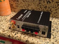
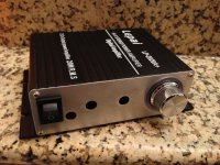
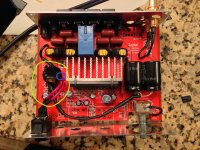
Ok, I finished my mods... With the exception of my MUSE input caps that are in the mail. I have some temp panasonics in there now.
Mods include:
Ferrite core inductors all around.
-Panasonic film caps for output.
-Relocated caps (the big ones, don't know what they are called) & inductor due to space limitations
-All tone controls wiped including bypass switch
-Volume pot rewired
-Install better thermal compound for heatsink
-Install 'better' rca inputs
-Removed annoying LEDs
-Removed 3.5mm input (will not be used)
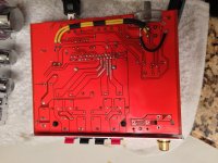
I think that's about it. The first pics don't have the big caps in them just in case anyone wants to see all the tone control wipes.
If you have any questions, let me know. This thing sounds great. I love it and it was very fun working on it.
Thanks to all the contributors for your help and write-ups.
Mods include:
Ferrite core inductors all around.
-Panasonic film caps for output.
-Relocated caps (the big ones, don't know what they are called) & inductor due to space limitations
-All tone controls wiped including bypass switch
-Volume pot rewired
-Install better thermal compound for heatsink
-Install 'better' rca inputs
-Removed annoying LEDs
-Removed 3.5mm input (will not be used)
I think that's about it. The first pics don't have the big caps in them just in case anyone wants to see all the tone control wipes.
If you have any questions, let me know. This thing sounds great. I love it and it was very fun working on it.
Thanks to all the contributors for your help and write-ups.
Attachments
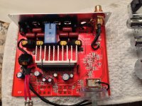
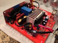
The output section mods:
I replace the inductors with Wurth 10uH 4.7A inductors (note I put 2 of those in wrong, the dot should be on the side that the amp chip is on - backwards will increase EMI).
The small ceramic SMD cap I replaced with 0.01uF WIMA caps (the two holes are meant for larger filter caps, but was a perfect fit for 5mm lead spacing as long as the other two caps are also 5mm).
The four output filter caps next to the inductors I replaced with 0.47uF film caps as the originals were probably ceramic.
The inductors + 0.47uF caps + 4 ohm speakers should give a cutoff of about 73kHz (I wish I could find the spreadsheet I used for that calculation).
I replaced the zobel components with 6R8 and 0.22uF film caps to give a frequency point of 106kHz (it should be a little higher than the primary filter cutoff so it doesn't have to deal with a lot of energy).
Attachments
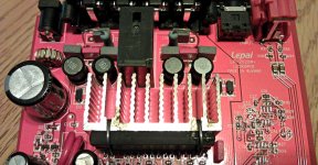
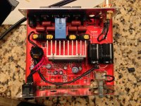
For anyone who is nervous about removing all the op-amp components, don't be. It doesn't matter one bit if you pull those traces off the board, and will give you some experience (removing them is much harder than soldering them in the first place). For the op-amps, I usually try to lie the soldering iron tip along all the pins on one side while gently prying up with a pin or tweezers. Once one side is lifted, hold the board on edge and heat the other side, the op-amp will fall off.
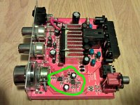
Everything in the green circle is fair game, as well as R18, R19, R20 and R21. Note that you WILL have to do more than that to have a functional amp, some sort of input bypass wiring, with or without the volume control.
Everything in the green circle is fair game, as well as R18, R19, R20 and R21. Note that you WILL have to do more than that to have a functional amp, some sort of input bypass wiring, with or without the volume control.
Attachments
To AJ and RedShift
This is some inspriational sh...t
like Alladin, rags to riches kinda dope
I wish my ugly duckling looked half as good as you guyes's'
AJ, are you just using the original volume pot? or did you use the tone pot.. it looks smaller to me.
Also, what are those rca "plugs" you guys bought called..
This is some inspriational sh...t
like Alladin, rags to riches kinda dope
I wish my ugly duckling looked half as good as you guyes's'
AJ, are you just using the original volume pot? or did you use the tone pot.. it looks smaller to me.
Also, what are those rca "plugs" you guys bought called..
Last edited:
Really tidy work AJ! I suppose I should post some more photos, though it's not nearly as tidy as yours.
Thanks redshift, I pretty much followed your lead.
To AJ and RedShift
AJ, are you just using the original volume pot? or did you use the tone pot.. it looks smaller to me.
Also, what are those rca "plugs" you guys bought called..
I am using the volume pot and the RCA plugs are just cheap-o ebay ones. Search RCA terminal.
Question:
Did you keep C2, the blue circle..
and Is there any stuff underneath the wires circled in the Green that you removed or replaced?
I didn't remove that cap. Check out this pic. Sorry the text is small. Oh, also, just to be safe, I isolated the pins on the volume pot with a dremel.
Attachments

Thx redshift..
Say, I want to remove that ugly power relay.... for fear that it may be affecting the sound.
Is this a very bad idea?
I really don't see much of an "explosion" risk... due to the low power output of the amp and the fact that there's a fuse "in" the ac adapter.
Say, I want to remove that ugly power relay.... for fear that it may be affecting the sound.
Is this a very bad idea?
I really don't see much of an "explosion" risk... due to the low power output of the amp and the fact that there's a fuse "in" the ac adapter.
Thanks redshift, I pretty much followed your lead.
I am using the volume pot and the RCA plugs are just cheap-o ebay ones. Search RCA terminal.
I didn't remove that cap. Check out this pic. Sorry the text is small. Oh, also, just to be safe, I isolated the pins on the volume pot with a dremel.
Cool stuff... I still can't get over how cleanly you desoldered the smd..
Did you use solder braid? or soldapult? or some fancy autopump..
And the Dremel thing... Do you mean Isolate the pins from the PCB? as in you're only basically gluing the pot to the board with solder notches, but they don't connect to the ground except by wire?
Thank you sir. I used my 15 year old Weller 40W. It's been through a lot but still does the job. After I removed each component, I followed up with a braid to clean it all up. I lifted some traces at the stubborn opamps but I don't plan on reinstalling them again so I don't care.
For the isolate thing. If you zoom into the pic I posted of the underside of the pcb, you can see where the copper traces coming into to the pot suddenly stop before they get to the pins. I still soldered the pot in place but the signal stays where the pins are so that the wires i used take all the signal. Does that make sense? I didn't want any rogue signals since I didn't really know what I was doing at first.
Hey is there something particular about that spot you chose to "ground the pot" at the top..
where the LED used to be..
and what is the difference between "analog" ground and "digital-power" ground
which is which on the PCB
Hmmm. I have no clue about the digital power ground. I only chose that spot for the pot ground because I used the original location for the pot pins under the pcb. No specific reason.
Hmmm. I have no clue about the digital power ground. I only chose that spot for the pot ground because I used the original location for the pot pins under the pcb. No specific reason.
Hrrrrrmmmmm......

I didn't bother cleaning mine with a desoldering braid after, I just remove the parts. Not as pretty, but just as functional.
As for analogue and digital ground, don't worry much about it. This PCB doesn't even remotely follow the recommended grounding in the TA2020 manual.
As for analogue and digital ground, don't worry much about it. This PCB doesn't even remotely follow the recommended grounding in the TA2020 manual.
Has any one tried m0ar-voltage?
Would it increase "bass" ?
my 12v 5amp came.. happy with it, well built for $8.99 shipped, does 12.6v unloaded. and it has a grounding pin wall side, luckily, much lower noise usually' with these than no ground pin 2 prong types.
jus. wonderin' f' shoulda' gotten a regulated 15v that could do 13.5v and swap some diodes.
Last edited:
- Status
- This old topic is closed. If you want to reopen this topic, contact a moderator using the "Report Post" button.
- Home
- Amplifiers
- Class D
- LP-2020A+ mod thread