So I decided to try a class-D project. Up till now it's mostly been tube...
I've been trying to estimate on a piece of paper, prior to building and testing, what switching frequency I can use when I know the on-off delays and on-off rise times of a given MOSFET. I would like to switch as high up in frequency as possible, but if I want to use all available voltage from 1% to 99% dutycycle, the fs cannot be so very high. Lets say on-off delays and on-off rise times totals 100ns, which will be the minimum pulse width, so 1%DC = 100ns. (Won't it?) The fs can be no more than 100kHz (10us).
Is it common to use higher fs, and simply let some voltage go unused, say having dutycycle vary from 10-90%?
Also regarding deadtime:
I find it a bit confusing that some say more than 40ns is detrimental (to THD) when most MOSFETs have total on-off times much more than that. The so called 'commutating current' in the LP-filter choke supposedly mixes this up as far as I understand (which is one of many parts of this I don't really understand well enough).
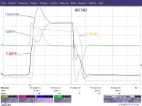
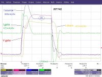
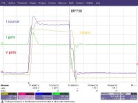
I've done some tests with IRF740 and 730 to measure on-off times, and the 740 need about 80ns to turn completely on and about the same (slightly longer) to turn off. I think the IRF640 is about the same. Yet it seems to me deadtimes of about 40ns is common with the 640.
I'm not trying to suck free info from anybody, just how I can theoretically calculate how high I can go in fs, as well as understanding deadtimes vs datasheet given delays. I have spend many hours reading various app notes, but the above still doesn't stick with my greys. Thx
I've been trying to estimate on a piece of paper, prior to building and testing, what switching frequency I can use when I know the on-off delays and on-off rise times of a given MOSFET. I would like to switch as high up in frequency as possible, but if I want to use all available voltage from 1% to 99% dutycycle, the fs cannot be so very high. Lets say on-off delays and on-off rise times totals 100ns, which will be the minimum pulse width, so 1%DC = 100ns. (Won't it?) The fs can be no more than 100kHz (10us).
Is it common to use higher fs, and simply let some voltage go unused, say having dutycycle vary from 10-90%?
Also regarding deadtime:
I find it a bit confusing that some say more than 40ns is detrimental (to THD) when most MOSFETs have total on-off times much more than that. The so called 'commutating current' in the LP-filter choke supposedly mixes this up as far as I understand (which is one of many parts of this I don't really understand well enough).
I've done some tests with IRF740 and 730 to measure on-off times, and the 740 need about 80ns to turn completely on and about the same (slightly longer) to turn off. I think the IRF640 is about the same. Yet it seems to me deadtimes of about 40ns is common with the 640.
I'm not trying to suck free info from anybody, just how I can theoretically calculate how high I can go in fs, as well as understanding deadtimes vs datasheet given delays. I have spend many hours reading various app notes, but the above still doesn't stick with my greys. Thx
"'ve done some tests with IRF740 and 730 to measure on-off times, and the 740 need about 80ns to turn completely on and about the same (slightly longer) to turn off. "
->Turn on and turn-off time depends on 2 parameters: MOSfet total gate charge and driver current. Q = I x t.
If the driver can supply enough current, you can turn it on as fast as you desire.
Q is a constant of your MOSfet, if I is increased, t will decrease, and vice versa.
->Turn on and turn-off time depends on 2 parameters: MOSfet total gate charge and driver current. Q = I x t.
If the driver can supply enough current, you can turn it on as fast as you desire.
Q is a constant of your MOSfet, if I is increased, t will decrease, and vice versa.
Thnx for reply.
No it will not turn on any faster than specs on datasheet. This is due to impedance between gate driver and MOSFET gate and parasitic capacitance.
I used a +-9A capable gate driver and about 1/4" distance between driver output and gate. (Plus a 5ohm SMD resistor in series with gate). Gate driver was UCC27322 and it was in turn driven by UCC25705 SMPS controller spoofed into running at a frequency and duty cycle according to potentiometer settings.
My tests got results about on par with datasheet claims.
I understand well the reasons for td-on, tr-on, td-off, and tr-off. I just don't quite grasp the theory to calculate the stuff in my first post. I guess I need to get comfy with reactive components a bit more. Something rather complex occurs in the dynamics when top and bottom side MOSFETs do their switching into a reactive load.
->Turn on and turn-off time depends on 2 parameters: MOSfet total gate charge and driver current. Q = I x t.
If the driver can supply enough current, you can turn it on as fast as you desire.
Q is a constant of your MOSfet, if I is increased, t will decrease, and vice versa.
No it will not turn on any faster than specs on datasheet. This is due to impedance between gate driver and MOSFET gate and parasitic capacitance.
I used a +-9A capable gate driver and about 1/4" distance between driver output and gate. (Plus a 5ohm SMD resistor in series with gate). Gate driver was UCC27322 and it was in turn driven by UCC25705 SMPS controller spoofed into running at a frequency and duty cycle according to potentiometer settings.
My tests got results about on par with datasheet claims.
I understand well the reasons for td-on, tr-on, td-off, and tr-off. I just don't quite grasp the theory to calculate the stuff in my first post. I guess I need to get comfy with reactive components a bit more. Something rather complex occurs in the dynamics when top and bottom side MOSFETs do their switching into a reactive load.
Last edited:
"I used a +-9A capable gate driver and about 1/4" distance between driver output and gate. (Plus a 5ohm SMD resistor in series with gate). "
The 5 Ohms will limit the peak current, so that your 9A driver does not deliver full current. Try decreasing the res and see how it gets faster.
BTW: Your MOSfets are not really "up to date"..
The 5 Ohms will limit the peak current, so that your 9A driver does not deliver full current. Try decreasing the res and see how it gets faster.
BTW: Your MOSfets are not really "up to date"..
Edit: parallel posting...
Just to clearify...I know even with a +-9A driver, I cannot get that out with a 5ohm resistor in there. (Besides...do we really believe this tiny package (driver) can actually source and sink 9A?) But I checked the gate current with a current transformer and the current was less than the potential 2A the driver could have given (10V drive).
Also when I say impedance between driver and gate, even directly coupling driver pin to pin, will still give an impedance that gives the delays.
Edit 2: the drain current and source currents are not same scale due to drain current measured with current transformer while source current using a 0.25ohm resistor.
Attachments
Last edited:
depends on gate type and package how well a MOSFET responds to increased drive - metal gate can be turned on/off much faster than poly-Si due to the lower sheet R - assuming parasitic LC doesn't limit 1st - which can be adressed by packaging
http://ixapps.ixys.com/DataSheet/IXZ316N60.pdf has single digit nS ton/off
http://ixapps.ixys.com/DataSheet/IXZ316N60.pdf has single digit nS ton/off
BTW: Your MOSfets are not really "up to date"..
Agreed....had a bunch on hand. But still, seems folks have been using similarly out of date -640s with very little deadtime - which is what gets my head spinning...
depends on gate type and package how well a MOSFET responds to increased drive - metal gate can be turned on/off much faster than poly-Si due to the lower sheet R - assuming parasitic LC doesn't limit 1st - which can be adressed by packaging
http://ixapps.ixys.com/DataSheet/IXZ316N60.pdf has single digit nS ton/off
Interesting MOSFET. Looks pricey
") switches in < 10ns! But almost 2nF Ciss!!!! Now the 9A gate driver will have to prove it's worth
switches in < 10ns! But almost 2nF Ciss!!!! Now the 9A gate driver will have to prove it's worthIf your gate driver is pulling to 10.5V, gate threshold is about 6.5V, so the difference is 4 V across the 5Ohm resistor -> 0.8A peak. BTW: The driver CAN deliver 9Amps peak.
Good point, will try less resistance.
There are certain stages of mosfet hard switch-on, in short:
1. initial gate to source charge up to threshold
2. di/dt stage, Vgate between threshold and plateu, I drain rising
3. dv/dt stage, Id constant, V gate constant at plateu, Vdrain falling
4. gate charge overdrive, V gate going up to driver's supply voltage, Rds-on falling.
Hard-switch-off goes the other way round. Now your dead time should only cover phases 2 and 3, in your scope shot they look like 30ns in total.
When the load is inductive, the inductor current may help to shorten phase 3 in some cases.
Edit: parallel posting...
Just to clearify...I know even with a +-9A driver, I cannot get that out with a 5ohm resistor in there. (Besides...do we really believe this tiny package (driver) can actually source and sink 9A?).
The package doesnt have to continuously supply 9 amps, its only for the first 100ns then there is no current flow.
Thnx for reply.The package doesnt have to continuously supply 9 amps, its only for the first 100ns then there is no current flow.
Yes indeed. If you look at the IRF740 it is sourcing for about 50ns and sinking for about 40ns. Being a TI device I had no reason to dis the driver, I duely appologize.
I wonder how the bonding wires handle the strain over time if this tiny package actually had to deliver +-9A over long periods of time. (I don't mean continous current, just the short spurts in and out of the gate). Coming from tube use, I keep getting surprised how much these miniature devices handle. It's a fascinating world of semiconduction.
- Status
- This old topic is closed. If you want to reopen this topic, contact a moderator using the "Report Post" button.
- Home
- Amplifiers
- Class D
- mosfet on-off delays vs fs and deadtime