First, I'm not an amplifier designer so I'm out of my element but this seems like a logical evolution to me. I hope this hasn't been posted or asked before. I see several threads relating to using multiple class D amplifiers in a system or using multiple stages to reduce THD but I have a different idea.
Since the output of a class D amplifier is driven by a clock, is there a way to separate frequency components before the output stage and add extra output stages for each speaker you intend to drive. One could possibly make a nearly zero phase sound system if the signal can be processed fast enough.
The idea is to have an input that is sampled at an appropriately high rate, say 400Khz or more. The sampling block would contain a discrete sample-and-hold for each output stage. For a two way speaker the amp would have two output stages driven off a single power supply. Each digital filter would then clock the appropriate output based on a comparator in the digital filter. I'm not a digital designer but it seems like it would be fairly easy to use a sample-and-hold --> bridge (DC analog of signal)--> comparator --> class D output.
The filter would need to take a sample then hold it. The comparator, synched to the sample clock, would then enable it's output based on the current signal. If the delta between current signal and previous sample is above a threshold this is a tweeter sample. If it's below a threshold this is a woofer sample. The comparator would enable it's output to drive the appropriate output stage in the same way a single channel class D does. I'm not even sure if this kind of circuit would work but the idea is to obtain an output drive signal based on the frequency of the input.
With the addition of more advanced signal processing before the crossover an inverse phase curve could be applied to correct for system group delay and/or one could also apply simple frequency EQ.
Additionally, If one can apply an inverse of the system group delay to the appropriate driver output it would effectively reduce it to near zero, minus any resistance or reactance between the speaker and the amp or other unaccounted for variables.
A zero phase system?
Is such a thing possible, likely, even in the works?
Seems to me like the next logical step in sound system evolution.
Yes an analog crossover will introduce a phase shift. A digital crossover can be done without delay. I believe it makes more sense to do the processing of the signal before the power stages (analog crossover or DSP) and let the power stages be less complicated. With digital sound processing (DSP) it can do similar to what you describe as its a mini computer with RAM that can compute this information (correct delays, crossover, and EQ) and output it to multiple power stages. Just my 2cents anyways.
Also most class d amps are going in the direction of self oscillation, means there is no fixed clock... it varies.
Also most class d amps are going in the direction of self oscillation, means there is no fixed clock... it varies.
Universe does not work like that.
The class D schemes that perform best don't use a fixed clock, but rather a self-oscillating free-running delta sigma approach (it compensates open loop gain automatically for power supply variations, it corrects the error of every cycle in the next cycle, and it corrects output filter resonance (ages ahead of triangle wave fixed frequency schemes), with just a few op-amps and a zero cross comparator).
To perform any form of useful digital filtering for speakers, a sampled input (either from digital source or from A/D conversion), RAM memory to store data, and a a high bit depth ALU (arithmetical logical unit, capable of signed addition and multiplication), are required. But delta sigma self oscillating class D takes an analog input, so D/A conversion is required too.
Your idea is very original, in this case the freq. carrier should be much higher, if you want to reserve a channel for 400Khz. in theory is a system already in use, such as in some measuring instruments. I believe that the problem of delay is already solved with the use of IIR in dsp. for class D, it all seems very simple (as it says EVA), strange that some engineers have lost 10 years, in an attempt to play a good self-oscillating hehe!
Regards
Regards
Of course there are many ways to do it, you can obfuscate it, or make it switched-capacitor-filter-like for 40dB SNR. But there will always be an inherently universal beauty in the way the real-world error components present at the output of the system (distortion) are dealt with in delta-sigma systems, and this beauty is lost in every other scheme. It's an analog calculator that can be made very accurate with little effort, replacing millions of logic gates.
btw: I've done some progress in DSP programming during the last year, I'm doing digital feedback loops among other things, that's why I don't show up often. I'm finding out what I already knew: Getting both high precision and high bandwidth from a digital loop is very expensive in terms of complexity, you can have either one, but not both. For example I use a digital loop for temperature limiting in amplifiers, because there are thermal time constants in the range of minutes involved (a real pain to do this with op-amps).
btw: I've done some progress in DSP programming during the last year, I'm doing digital feedback loops among other things, that's why I don't show up often. I'm finding out what I already knew: Getting both high precision and high bandwidth from a digital loop is very expensive in terms of complexity, you can have either one, but not both. For example I use a digital loop for temperature limiting in amplifiers, because there are thermal time constants in the range of minutes involved (a real pain to do this with op-amps).
First, I'm not an amplifier designer
Hi,
Or a speaker designer or anyone au fait with the real issues regarding
phase and group delay and the consequences of digital manipulation.
Not that I know that much about it, because its pretty inconsequential
in the big scheme of things that matter regarding quality reproduction.
rgds, sreten.
Hi,
Or a speaker designer or anyone au fait with the real issues regarding
phase and group delay and the consequences of digital manipulation.
Not that I know that much about it, because its pretty inconsequential
in the big scheme of things that matter regarding quality reproduction.
rgds, sreten.
Huh?
Universe does not work like that.
The class D schemes that perform best don't use a fixed clock, but rather a self-oscillating free-running delta sigma approach (it compensates open loop gain automatically for power supply variations, it corrects the error of every cycle in the next cycle, and it corrects output filter resonance (ages ahead of triangle wave fixed frequency schemes), with just a few op-amps and a zero cross comparator).
With a high clock rate, I'm thinking 2 Mhz or a multiple of the lowest oscillator frequency, it could easily be integrated into a self -oscillating design. The crossover would simply act as an OR switch for the drive clock of an existing amp. Duplicate the output stage for a tweeter and add some OR logic to select which output to clock based on the crossover. Seems simple enough if the drive oscillator is high enough to accurately separate the samples.
Eh? Maybe?
I guess the "proof is in the puddin". I'll have to build one.
 I was hoping someone else would get all excited and do it for me.
In any 2-way system, poles and zeros at very specific locations are required in each output for proper acoustical sum (at least for matching the acoustical phase of both drivers on-axis across crossover frequency region, the best compromise). I have already told briefly how the samples have to be processed, it's not just a matter of selecting them, frequency division requires complex math and memory of previous samples to calculate new LF and HF samples from input samples.
Last edited:
In any 2-way system, poles and zeros at very specific locations are required in each output for proper acoustical sum (at least for matching the acoustical phase of both drivers on-axis across crossover frequency region, the best compromise). I have already told briefly how the samples have to be processed, it's not just a matter of selecting them, frequency division requires complex math and memory of previous samples to calculate new LF and HF samples from input samples.
So you're saying the error that would occur with two different clocks would induce random phase and probably frequency distortion at the output because there is no way to synch the samples?
I'm still convinced there is a way to do it given enough time and consequently experience. I suppose only time will tell. Thank you for your input, no pun intended...
No, I'm saying that your method for separating HF and LF is not realistic, probably because you don't have enough understanding about physical systems. The system needs to know not only current delta but also previous deltas, and previous outputs too (if IIR), and only then LF and HF samples can be calculated by multiplying these factors by filter coefficients and adding the results, there is no simpler way to do it. Read about digital filters. Anything else won't act as a filter but as some kind of creative signal distorter.
What Eva is saying is you can't take one sample and determine if its a bass note or high hat. It needs to take many many samples and process it as a whole to extract the high and low signals. When you do this digitally its called digital sound processing. A high quality DSP is a mini computer in a sense with enough ram and clock speed to do the processing with little latency.
A single sample does not contain a frequency. You need to take many over a certain period and then process it to figure out the frequency.
A single sample does not contain a frequency. You need to take many over a certain period and then process it to figure out the frequency.
Hi,
What is called here "logical evolution" is just ill-informed nonsense.
The idea that each sample is related to a frequency range and can be
steered towards an appropriate digital amplifier for an active multiway
speaker indicates a total lack of understanding of the relevant issues.
Same with the idea you can somehow similarly fix group delay on a
sample to sample basis, you have no idea what you are talking about.
rgds, sreten.
Last edited:
Hi ,
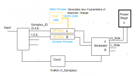
if I understand the idea of "Siggma", this is pic of the simplified concept.
independent of knowledge of Siggma, and feasible, I vote your idea because it shows an open brain.
the input side, this system is called "vertical acquisition", I mean that the samples are rotated as channels, then go used a transverse (rotation matrix) to take continuous samples.
As I said, the concept of the multiplex is used, it may be too old.
---------------------
for those who have no experience with these systems, it is obvious that at the input of the IIR filter, there is a circular buffer. the number of samples to be processed, must have a sufficient quantity, dependent on the frequency of the filter.
Regards
Attachments
Last edited:
No, I'm saying that your method for separating HF and LF is not realistic, probably because you don't have enough understanding about physical systems. The system needs to know not only current delta but also previous deltas, and previous outputs too (if IIR), and only then LF and HF samples can be calculated by multiplying these factors by filter coefficients and adding the results, there is no simpler way to do it. Read about digital filters. Anything else won't act as a filter but as some kind of creative signal distorter.
maybe you're confusing FIR (finite impulse response) and IIR (infinite impulse response) it does not introduce significant delay, just because it works in a different way from the FIR. (which requires to compute the result, from a preset number of samples, which #samples depend on the frequency). IIR instead, which uses an infinite loop even if only on two consecutive sampling points (called real / imaginary). This algorithm use the coefficient vector and is really simple if you want to develop in C / C + + on PC,just for try,if you have a good knowledge of mathematics.
regards
- Status
- This old topic is closed. If you want to reopen this topic, contact a moderator using the "Report Post" button.
- Home
- Amplifiers
- Class D
- Multi stage output digital bi amp?