not finished yet


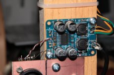
Heatsinks on top of the chips?
TPA3118 thermal solution is through the underside. Usually you see an array of holes on the underside of the board beneath the chip.
J.
Heatsinks on top of the chips?
TPA3118 thermal solution is through the underside. Usually you see an array of holes on the underside of the board beneath the chip.
J.
I've used about 10 of those boards, without any added heatsinks. They barely get warm, even when powering 2 ohm loads at high volumes. (Granted I used 19 volt laptop power bricks, you are using a 24 volt supply)
The heat-sinks you added will not do any harm, but they are probably not needed. As already described, the 3118 internally is thermally connected to the bottom of the chip. That is soldered to the PC board for its cooling.
The 3116 chip needs a heatsink on its top... It is the exact same silicon, but internally upside down from the 3118. Your boards use a 3118.
In addition, the cooling fan you added will likely have nothing to do, as there is hardly any heat generated in your amplifier. (Suggestion, try the amp, at full power without the fan running, and see if the heat-sinks you added get warm at all. Odds are they will be very cool, without any additional cooling needed.) Unless your power supply generates lots of heat, and requires cooling, the fan will make more noise than it is worth.
Joe L.
Mine are barely taxed. A pair of Asus 19V laptop bricks power them in pairs, one amp per driver.
When XRK did some tests he attached them to some substantial heatsink and drove them hard through a meaty resistor.
http://www.diyaudio.com/forums/clas...18d2-boards-modding-comes-25.html#post4585203
Interesting he mentions them being warm at idle with 24V PSU but not with 19V.
Picture of anti-pop fix
I have read most all the posts related to the anti-pop cap,resistor/diode fix....but I am still not sure the best way to attempt to place/solder on the sanwu pbtl mono board....as I guess the board won’t handle many mishaps /redo I was wondering if anyone can post a actual picture of the board with the fix implemented ( I will also first remove r27 to drop gain to 20db)
Thanks in advance
All I found about this amp is hereMaybe I'm inaccurate, using wrong term, but the amps both shut down for a few seconds then came back on for a few seconds, then shut down for a longer time, then came back on, I left the volume unchanged through this until after second shutdown. I was playing the song Feel It Still, by Portugal The Man, modern alternative music. from my iPhone 6+.
These amp is with TPA3116 chip - this thread is about 3118 chip amps.All I found about this amp is here
")
The "top" of the cap is soldered to one of the empty pads that was left after removing R27 (the pad that's connected to the Vreg output of the chip, along the trace that goes to the 10k pull-up resistor in-between the input and mute "connectors").
The "bottom" of the cap is soldered to the other track coming from the mute connector - i just scraped off the soldermask on that trace.
The diode is a small Schottky that i scavenged from a dead laptop mainboard, and the parallel resistor is the 100k R30 that's already on the board
Note that i added a sliver of kapton tape under that ceramic cap, to avoid either of its ends getting shorted to the adjacent ends of R28 and R30, which go to ground.
Thx kron...can’t really tell where the cap is connected on both ends?....it appears both sides are on the double ground pad to th left of the last 2 smd resistors.....
the diode ( what kind of diode did you use) is clear but no parallel resistor?
Thx
Lance
Thx khron, think I got it. Some last questions
Any reason why I could not go further up that trace towards the 10k r26 and angle the cap down onto the lower mute return pad? ( I assume r26 now serves no function)
Then the diode from the same lower mute return pad to the exposed circular pad below that in the grounds section?
The 100k (r30) is enough for appropriate/ enough turn on delay?
For the cap a x7r 1uf ceramic 1206 size OK?
Any smd schottky ( any voltage, etc) sod-128 ok?
Thx again
That assumption could be incorrect, but that only depends on whether you will or won't be using that mute input.
I followed this schematic. See the datasheet for the pinout of the signals.
I used a 1206 cap - can't remember whether it was a 4.7uF or 10uF though. I went with the bigger value to "make up for" not bothering increasing that 100k resistor.
By the looks of it, the diode i used was a SOD-323 package, but that was only because i didn't want to bother shoehorning in a bigger-packaged one there. Anything over 30-40v should do just fine.
Any case you can recommend to house a TPA3118D2 board?
I imagine there should be many, but I can't find them on eBay.
Really?
It's a small board, it will fit pretty much in any case.
And we cannot possibly know about your setup, what else needs to fit in the enclosure.
Try search for amplifier enclosure and make your pick.
Really?
Really. Have you looked for such cases in eBay or Google?
It's a small board, it will fit pretty much in any case.
A small board with at least three precision holes to drill.
And we cannot possibly know about your setup, what else needs to fit in the enclosure.
Nothing else goes into the box, except for the output speaker connectors.
Try search for amplifier enclosure and make your pick.
Looking for amplifier enclosures won't get me one designed for this board.
The ones for the TDA3116 are different, and they are also acrylic, which is too fragile and does shield RFI.
With all this thread pages I assumed this question had already been solved.
Attachments
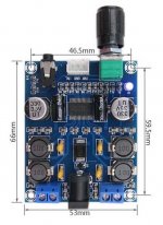
Oh, I see. So you have that version with the potentiometer and aux in at the front and power jack at the back.
I would say that get a bit bigger enclosure than the board is, and mount the board to the front panel, so two holes to be drilled. Then get a separate panel mounted dc-jack for the power.
I would say that get a bit bigger enclosure than the board is, and mount the board to the front panel, so two holes to be drilled. Then get a separate panel mounted dc-jack for the power.
- Home
- Amplifiers
- Class D
- Cheap TPA3118D2 boards, modding them and everything that comes with it