Hello,
just ordered two stereo amps "ALLO VOLT AMP Stereo Amplifier classe Class D TPA3118D2 2x25W / 8 Ohm". Do you know, if i power them from the 12V PC power supply, sound is degrading? I have a 19V laptop brick but would use the PC power supply, same ground, simplicity.. etc.
Thanks!
just ordered two stereo amps "ALLO VOLT AMP Stereo Amplifier classe Class D TPA3118D2 2x25W / 8 Ohm". Do you know, if i power them from the 12V PC power supply, sound is degrading? I have a 19V laptop brick but would use the PC power supply, same ground, simplicity.. etc.
Thanks!
Ok, settled on config (I think), just thought I'd post this to see if anyone thinks I'm wasting my time on the input caps. Would it be better to add 1,000 uF across DC input terminals or replace 4 input caps with higher quality 220uF Panasonic SMD caps?
I'm gonna swap the inductors for larger 33uH Wurth (2.5A), as I have space for them in the enclosure and the coils seem to be the most worthwhile mod according to this thread. I'm using 8R speakers, feeding the amp with an Echo Dot (Amazon). Using mute as the on/off switch, although my enclosure has an 120VAC on/off switch. Typical use is moderate listening levels but I like to crank it up now and then. Both '3118's are powered by a single 24VDC/9A power supply linked earlier in this thread.
I'm gonna swap the inductors for larger 33uH Wurth (2.5A), as I have space for them in the enclosure and the coils seem to be the most worthwhile mod according to this thread. I'm using 8R speakers, feeding the amp with an Echo Dot (Amazon). Using mute as the on/off switch, although my enclosure has an 120VAC on/off switch. Typical use is moderate listening levels but I like to crank it up now and then. Both '3118's are powered by a single 24VDC/9A power supply linked earlier in this thread.
My guestimate is that the current caps are sufficient with that load.Ok, settled on config (I think), just thought I'd post this to see if anyone thinks I'm wasting my time on the input caps. ................ I'm using 8R speakers.................Both '3118's are powered by a single 24VDC/9A power supply linked earlier in this thread.
The better the power supply and the shorter the leads from it to the board, the less need for extra caps.
I need to implement your antipop-design, but I'm not sure how. I mean I find the corresponding pins from the board, but am I supposed to replace existing components or just add what you have here? I took a closeup about the situation so maybe you guys could help me.
And what about the used components? Is there some specific requirements for the resistor, capacitor and diode? Can i use a basic through hole-resistor and electrolytic capacitor?
Need to bump my question, sorry.
I finally got my amp working to my requirements. First I adjusted the gain, tried 20dB first, but it was too low for me. Good that I didn't throw the 100k resistor away when I desoldered it. Raised the gain to 26dB and now the output is quite good, I'm driving a single Dayton audio ND91-4 so it demads quite a lot power. But with this setup, I can tease the 3,5" to it's limits, at least the cone movement looks like it

But now to the actual question about the anti-pop, how do I implement it to this? The biggest problem is starting up; the poor little driver moves so much that I feel sorry for it
I know there's the mute but I don't want to use it because I already have one switch for power. This is a portable design so I want to keep it simple.You are indeed supposed to add / replace the appropriate components there (since there's no diode there, or the capacitor to GVDD).
The connection between R26 and R27 should give you plenty of choices where to connect that capacitor; you can even scrape the soldermask off that trace, if needed (you may have to remove that 10k R26 though).
You'll want to replace R30, or test to see if the existing 100k gives you enough of a delay with whatever value cap you choose. And then see where you can squeeze a little Schottky diode next to it (or even on top of it, if needed).
I just found this nice looking 2.1 plate amp based on 2x 3118 chips:
Any of you have hands on experience with it?
TPA3118 60W+30Wx2 2.1 HIFI Digital Subwoofer Power Amplifier Board W/ 2.0 Output | eBay

Any of you have hands on experience with it?
TPA3118 60W+30Wx2 2.1 HIFI Digital Subwoofer Power Amplifier Board W/ 2.0 Output | eBay
I just found this nice looking 2.1 plate amp based on 2x 3118 chips:
Any of you have hands on experience with it?
TPA3118 60W+30Wx2 2.1 HIFI Digital Subwoofer Power Amplifier Board W/ 2.0 Output | eBay
A few have bought them but no feedback from them. Someone's project over on PE forums uses it in a portable foam core build.
The Foam Core Forte - Techtalk Speaker Building, Audio, Video Discussion Forum
J.
You are indeed supposed to add / replace the appropriate components there (since there's no diode there, or the capacitor to GVDD).
The connection between R26 and R27 should give you plenty of choices where to connect that capacitor; you can even scrape the soldermask off that trace, if needed (you may have to remove that 10k R26 though).
You'll want to replace R30, or test to see if the existing 100k gives you enough of a delay with whatever value cap you choose. And then see where you can squeeze a little Schottky diode next to it (or even on top of it, if needed).
Thanks!
The R26 was good as it is, but I needed to replace the R30 with 820k because I was using a 1uF capacitor.
A few have bought them but no feedback from them. Someone's project over on PE forums uses it in a portable foam core build.
The Foam Core Forte - Techtalk Speaker Building, Audio, Video Discussion Forum
J.
That was my foam core project. I'm still using it on a daily basis for music in our kitchen. I'm more than happy with it. Everyone who has heard it has said that it sounds great too, so I guess the amp is a good implementation of the 3118. It has plenty of power to drive the speakers with no distortion. For ~$30 you can't beat it. One thing to note though, like most cheap 2.1 amps the subwoofer volume is not in sync with the main volume. I use it with a separate Bluetooth module so this is not an issue for me.
That was my foam core project. I'm still using it on a daily basis for music in our kitchen. I'm more than happy with it. Everyone who has heard it has said that it sounds great too, so I guess the amp is a good implementation of the 3118. It has plenty of power to drive the speakers with no distortion. For ~$30 you can't beat it. One thing to note though, like most cheap 2.1 amps the subwoofer volume is not in sync with the main volume. I use it with a separate Bluetooth module so this is not an issue for me.
As a "plate" implementation that (usually, I guess) matters a lot less than if it were used as a typical cupboard/desk top amp.
Good to see some feedback on it too. I'd tried to match Aliexpress purchases to members of various forums/fora.
J.
Last edited:
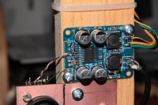
I finally managed to put my first two of these little TPA3118 boards to (good?) use. The "twist" is, i made them balanced-input
All that needed was to "carve out" a small island around the ground-end of the inverting input coupling cap, thereby disconnecting it from ground, and hooking up the "cold" signal wire
More details and photos over on my blog, for whoever's interested
All that needed was to "carve out" a small island around the ground-end of the inverting input coupling cap, thereby disconnecting it from ground, and hooking up the "cold" signal wire
More details and photos over on my blog, for whoever's interested
Mmm... Since those 0603 components are small to begin with, and MLCC's are brittle / fragile anyway, i preferred to leave it mounted as it was.
Those two little cuts were quite trivial though, the whole operation was done in less than a minute Including scraping off the solder-resist from the leftover input "island", to give a larger solder blob to solder the wire to.
[edits]
PS: Those CAT5 wires are solid-core anyway, so that would've just been (potentially) some extra stress on an 0603, and that seemed unnecessary.
PS2: Might as well attach that photo here, for those who can't be bothered to click on a link
Those two little cuts were quite trivial though, the whole operation was done in less than a minute
Including scraping off the solder-resist from the leftover input "island", to give a larger solder blob to solder the wire to.[edits]
PS: Those CAT5 wires are solid-core anyway, so that would've just been (potentially) some extra stress on an 0603, and that seemed unnecessary.
PS2: Might as well attach that photo here, for those who can't be bothered to click on a link
Attachments
Last edited:
Yes, but you need somewhere to mount those, too
Even if we were to ignore the connector block legs poking out on the bottom (which would've needed drilling another hole), i would've had to (also) "cut out" the ground pad for the input "connector", on both sides of the board, to isolate it from the ground planes, AND isolate the ground end of that coupling cap, AND run a short little wire between those.
Proper? Nope, not even close But was it the quickest, easiest and least "traumatic" solution? Hell yeah...
Even if we were to ignore the connector block legs poking out on the bottom (which would've needed drilling another hole), i would've had to (also) "cut out" the ground pad for the input "connector", on both sides of the board, to isolate it from the ground planes, AND isolate the ground end of that coupling cap, AND run a short little wire between those.
Proper? Nope, not even close
But was it the quickest, easiest and least "traumatic" solution? Hell yeah........quickest, easiest
Power and output are also soldered and a connector block is not luxury at those positions (certainly with possible mechanical stress AND 2 wires per position). Also the use of standoffs is recommended to avoid mechanical stress on SMD parts. I count 4 holes and see 2 wood screws...
Anyway, do what you think is best. I hear many times "I will correct later" and almost never see that happen. It is just losing time to deliver sloppy work as one has to to do the same thing twice.
Last edited:
I made sure to fill those holes with solder before adding the wires, so they're not only "surface-soldered". That, and it's a 'fixed installation", and the cabling is quite securely zap-strapped, with some length left to act as strain-relief (see the other, wider-angle photos there).
Like i said, i know it's not "commercial equipment grade", and this was an almost-100%-free project to reuse some stuff i had lying around
PS: One other reason (or a couple others, actually) for not using connector blocks is that i didn't have any small-enough ones in stock, nor was i willing to bother searching for some, spend more money on those, and wait for delivery. I got these things done in a couple afternoons / evenings, and they work
I'm designing a TPA3118D2 board, mostly by reference design, but I still have some questions. I've been reading a lot in this and the 3116 thread and there are still some question that needs answers. First off I can say that I'm going to use it for a 2.0 system and will therefore not need the sync function. Should I ground or leave the SYNC pin open?
I have not seen much use of the pot for setting PLIMIT here but I'll stick with it just for safety so I am wondering what load I can use while setting it. The speakers are 8 Ohm and I would assume most 8 Ohm resistors will burn pretty quickly, atleast before I have time to adjust the pot.
They have a switch, S1, at the SDZ input to shut down the IC, is there any reason why I shouldn't put it in series with my power source instead?
Lastly, my biggest concern about my design... There will be two single ended inputs (3.5mm's) using a switch to choose one. The output from the switch will be regulated using a potentiometer (volume knob) and then into the 1 uF capacitors before the right and left input. Is there any reason I should even try this or will the signal quality be degraded too much? If I choose to use a simlilar build to the preamp, that was not too long ago proposed by DUG in post #2216. The one that inverting the positive signal using an OPamp to get differential signals. Should I place this closely to the inputs (3.5mm's) or close to the IC for best effect?
It is very late here in Sweden right now so hopefully it is somewhat comprehesible! Also thanks in advance for any answers!!
...
Lastly, my biggest concern about my design... There will be two single ended inputs (3.5mm's) using a switch to choose one. The output from the switch will be regulated using a potentiometer (volume knob) and then into the 1 uF capacitors before the right and left input. Is there any reason I should even try this or will the signal quality be degraded too much? If I choose to use a similar build to the preamp, that was not too long ago proposed by DUG in post #2216. The one that inverting the positive signal using an OPamp to get differential signals. Should I place this closely to the inputs (3.5mm's) or close to the IC for best effect?
It is very late here in Sweden right now so hopefully it is somewhat comprehensible! Also thanks in advance for any answers!!
I run the differential signal from another box (preamp) through a twisted shielded pair
I use 10uF caps on the 3116 inputs. Does the low end good.
My first preamp was basically a couple of buffered 2K pots to keep resistor noise low.
no noise.
MHO
- Home
- Amplifiers
- Class D
- Cheap TPA3118D2 boards, modding them and everything that comes with it