Hi, I'm making an amplifier based on the L12-2 amp and a 6N3 Buffer Pre Amp. And I've also bought an toroidal transformer (25-0-25). But the thing is that I'm not quite sure how to make an output of -50VDC / GND / +50VDC for the amplifier.
I've came across this schematic :

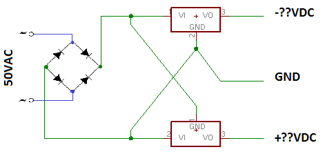
So let's say that my transformer is wired in series, giving me an output of 50VAC, sending that voltage in a bridge rectifier and make a this negative voltage generator (like the picture). Is the output of the generator going to be -25VDC / GND / +25VDC or -50VDC / GND / +50VDC (Assuming that the picture below is the roughly made schematic without filter caps)???
Thanks
Le Pick
I've came across this schematic :
So let's say that my transformer is wired in series, giving me an output of 50VAC, sending that voltage in a bridge rectifier and make a this negative voltage generator (like the picture). Is the output of the generator going to be -25VDC / GND / +25VDC or -50VDC / GND / +50VDC (Assuming that the picture below is the roughly made schematic without filter caps)???
Thanks
Le Pick
Attachments

TBH, those schematics look like a train wreck to me.
The only way I know of to obtain 50-0-50 from a 25-0-25 transformer is via a voltage doubler type of circuit.
The only way I know of to obtain 50-0-50 from a 25-0-25 transformer is via a voltage doubler type of circuit.
^^See post #2.
Have a closer look at those schematics. You'll see that the regulators are acting on the exact same input voltage, with only the polarity signs reversed. And so while the voltage between GND and one output will be correct, the voltage between GND and the other output will only be the voltage drop across that regulator.
Yes, a doubler will lower the current delivered. You really need a transformer bigger than 35-0-35.
This is a dual thread of a 50V PSU question that has already been addressed.
http://www.diyaudio.com/forums/power-supplies/215853-50v-power-supply.html
http://www.diyaudio.com/forums/power-supplies/215853-50v-power-supply.html
Indeed, because I had another idea and also the other thread have more replies...This is a dual thread of a 50V PSU question that has already been addressed.
http://www.diyaudio.com/forums/power-supplies/215853-50v-power-supply.html
Hi , you can keep the 25-0-25 V AC trafo for future projects .
The bridge rectifier + lots of caps may not be optimal , a big fat cap
is also visually more ' muscular' 😉
Look for 10000 uF / 63 VL for a 50 V DC application ( there are the surge peaks and the variations of the mains )
Also 15-20 K uF ...you just need two , one for positive rail and one for neg.
The bridge rectifier could be the square 25 A with faston type pins .
Last edited:
- Status
- Not open for further replies.
- Home
- Amplifiers
- Class D
- Negtive Voltage ?????