Anyone have experience with them? I mean toroidal inductors wounded on non-ferrous material like wood, plastic or simply air.
Some quick google I came across with these:
http://engineering.dartmouth.edu/inductor/papers/pesc2007b.pdf
http://thayer.dartmouth.edu/inductor/papers/apec2008a.pdf
Unfortunately their inductance are 100 times smaller than what we need for class D amplifier output filter. But the construction idea look promising.
Any idea?
With an air core, even if inductor is toroidal, the number of turns required becomes quite high resulting in problems with high winding capacitance and wire resistance.
Low permeability iron powder RF materials like micrometals -2 (u=10) allow for good compromises between linearity, turn count and capacitance.
It's high permeability cores (like 26 material with u=75) what result in poor linearity, but it's not a good idea to go down to the u=1 permeability of the air either.
It's high permeability cores (like 26 material with u=75) what result in poor linearity,.
Really? I didn't know that. What makes that so?
thanks
gene
With an air core, even if inductor is toroidal, the number of turns required becomes quite high resulting in problems with high winding capacitance and wire resistance.
For example a 25mm height, 50mm outter diameter toroid, with 88 turns of AWG20 wire, yields 0.23 ohm. Is it very bad?
Ness Engineering Tech Data - Toroid Formulas
Really? I didn't know that. What makes that so?
thanks
gene
Besides different shape of the magnetization curves, with u=75 you will typically also end up in a design with pretty low number of turns (nice for Rdc), but you will typically end up with a design that drives the core to higher flux densities (not nice...).
With lower permeability you can find a better trade off between Rdc and flux density.
Given the same core size and turn counts, a material producing 10 times more inductance than air is always going to exhibit better linearity and less losses than one producing 75 times more inductance than air. The extra inductance always comes at a cost. At high current (magnetizing force) the 75u material losses extra permeability and ends up being 10u too, while the 10u material just stays at 10u all the way.
See this figure:
And this is the trick with iron powder toroids")
For SMPS, chokes with inductance smoothly falling as current increases are useful, they prevent discontinuous mode and reduce ripple and stress at low current, but for class D they aren't useful.
See this figure:
An externally hosted image should be here but it was not working when we last tested it.
And this is the trick with iron powder toroids
For SMPS, chokes with inductance smoothly falling as current increases are useful, they prevent discontinuous mode and reduce ripple and stress at low current, but for class D they aren't useful.
Last edited:
Hi Eva,
I agree on the choice, but do not feel comfortable with some simplifications.
To compare in a fair way you must not compare same number of turns.
From application view you will need a certain inductance.
Consequently with a material of u=10 the number of turns will be higher by factor sqrt(7.5) compared to the design with u=75.
Unfortunately the same applies for the magnetizing force.
Fortunately the material with u=10 allows not just factor sqrt(7.5) but factor 20 higher magnetizing forces without much dropping and consequently is the more fortunate choice for class D.
Air cored inductors work great; I applied them in NPX (former Philips) TDA8920 class d amps.
DC resistance is to pay attention to, but capacitance is a non-item because of the very low source impedance and the "few" number of windings.
Inductance is linear as is to be expected from air cored inductors.
DC resistance is to pay attention to, but capacitance is a non-item because of the very low source impedance and the "few" number of windings.
Inductance is linear as is to be expected from air cored inductors.
What value of inductance are we talking about?
Madisound or Parts-Express might have what you need. They have lots of air-core inductors for speaker crossovers, too (along with vary-large-value film caps).
But for a small-valued one, you could so-easily wind your own. Here is a good air-core inductor calculator:
Pronine Electronics Design - Multilayer Air Core Inductor Calculator
For lower resistance, just use larger-gauge magnet wire. I did a 2.8 mH crossover coil with something like 130 feet of 10-gauge magnet wire and it was around 15 milliohms or less, if I recall correctly. (Yes, it was very large and heavy, and the wire alone was about $40 per coil, but would probably be much more costly now.)
Let's say inductance value of 30uH, that is 0.03mH.For lower resistance, just use larger-gauge magnet wire. I did a 2.8 mH crossover coil with something like 130 feet of 10-gauge magnet wire and it was around 15 milliohms or less, if I recall correctly. (Yes, it was very large and heavy, and the wire alone was about $40 per coil, but would probably be much more costly now.)
In case of toroidal structure, the inner diameter limited the size of wire to be used if we keep it single layer. 10 gauge is seriously thick! How would you managed to pull it tight??
I did a 2.8 mH crossover coil with something like 130 feet of 10-gauge magnet wire and it was around 15 milliohms or less, if I recall correctly. (Yes, it was very large and heavy, and the wire alone was about $40 per coil, but would probably be much more costly now.)
The 15mohm could only apply to very low freqs. Above a kilohertz or so this would get very lossy due to proximity effect
Air core inductors leak all the field out, this can cause potentially destructive cross-talk problems in class D.
Air core inductors in passive crossovers suffer from crosstalk too, resulting in deviation from expected frequency response.
Ferrous materials in close proximity to air core inductors ruin their linearity.
Some "field confinement" is always good.
Air core inductors in passive crossovers suffer from crosstalk too, resulting in deviation from expected frequency response.
Ferrous materials in close proximity to air core inductors ruin their linearity.
Some "field confinement" is always good.
The 15mohm could only apply to very low freqs. Above a kilohertz or so this would get very lossy due to proximity effect
Yeah. It was for the bass.
Air core inductors leak all the field out, this can cause potentially destructive cross-talk problems in class D.
Air core inductors in passive crossovers suffer from crosstalk too, resulting in deviation from expected frequency response.
Ferrous materials in close proximity to air core inductors ruin their linearity.
Some "field confinement" is always good.
I've never known you to be wrong, so I'll buy that. (Mine were used for the passive crossovers for some Magnepan MG-12 speakers and are well-away from both ferrous materials and other components and conductors.)
But if ferrous materials in close proximity to air core inductors ruin their linearity, then how does a ferrous-material core in an inductor not ruin its linearity?
Isn't this offers confinement to the field?Some "field confinement" is always good.
Given the same core size and turn counts, a material producing 10 times more inductance than air is always going to exhibit better linearity and less losses than one producing 75 times more inductance than air. The extra inductance always comes at a cost. At high current (magnetizing force) the 75u material losses extra permeability and ends up being 10u too, while the 10u material just stays at 10u all the way.
Oh - you mean linearity of the inductor vs power, and not necessarily linearity of the output signal. Maybe it's possible to design an output inductor that stays in the flat portion of the curve and use larger permeability.
I've never known you to be wrong, so I'll buy that. (Mine were used for the passive crossovers for some Magnepan MG-12 speakers and are well-away from both ferrous materials and other components and conductors.)
But if ferrous materials in close proximity to air core inductors ruin their linearity, then how does a ferrous-material core in an inductor not ruin its linearity?
When a core is used, at least you are expected to dimension it to avoid saturation. This is not the case, for example, when a passive filter with air core inductors is close to a ferrous metal plate. This increases inductance but only at low current. If it's not ferrous, then inductance just decreases.
Last edited:
When a core is used, at least you are expected to dimension it to avoid saturation. This is not the case, for example, when a passive filter with air core inductors is close to a ferrous metal plate. This increases inductance but only at low current. If it's not ferrous, then inductance just decreases.
(SOrry if this is somewhat off-topic.)
OK. Thanks. I already assumed we would avoid saturation and was worried more about the hysteresis effect.
For an analog filter for the bass part of a speaker crossover, assuming no nearby metal, wouldn't an air core inductor have no possibility of hysteresis distortion while a ferrous core inductor would have hysteresis distortion (or at least the possibility of it)? I guess what I'm actually wondering is if that could be a significant difference between them or not, or significant-enough to sway component selection toward the air core type, for a one-off situation where sound quality is the only priority.
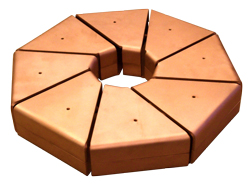
YG Acoustics does use air core toroidal inductors in their loudspeak crossover network. But those are in multi-layer construction and not suitable for class D amplifier output filter due to their high inner-winding capacitance.
http://www.ygacoustics.com/UploadFiles/file/PDF/YG%20Acoustics%20ToroAir%20Brochure.pdf
http://www.ygacoustics.com/UploadFiles/file/PDF/YG%20Acoustics%20ToroAir%20Brochure.pdf
Hysteresis depends on the way the core material is used.
In a high permeability "closed" magnetic circuit, like ferrite cores with very small gap or high permeability iron powder cores, hysteresis becomes easy to view on oscilloscope.
However, if ferrite is just used as a big center rod to collect field lines of all turns (and get inductance proportional to n^2 regardless of winding dimensions) and the magnetic circuit is left open (and thus low permeability), then oscilloscope shows no appreciable hysteresis. Low permeability iron powder toroids produce the same effect, no visible hysteresis.
In general, non-linearity is a consequence of high permeability because obtaining high permeability involves pushing materials and its internal mechanisms into non-linear territory. In low permeability inductor designs, more energy is stored in the air and less in the core material itself.
- Status
- This old topic is closed. If you want to reopen this topic, contact a moderator using the "Report Post" button.
- Home
- Amplifiers
- Class D
- Air core toroidal inductor for class D amp output?