I have been designing a class D amp based on the IRAUDAMP7S rev 1.0 and I cant manage to make it work.
It seems that when the MOSFETs are connected the power supply shows as being shorted.
What are the things that could cause this? I have checked for shorts in pcb, modified dead time and didnt seemed to help.
Thanks in advance =)
Edit: Typo mosfet is IRFI4019H
It seems that when the MOSFETs are connected the power supply shows as being shorted.
What are the things that could cause this? I have checked for shorts in pcb, modified dead time and didnt seemed to help.
Thanks in advance =)
Edit: Typo mosfet is IRFI4019H
Last edited:
Hi
Do you have a oscilloscope ?
If yes , upload you captures.
If not , try to get one .it´s essential.
----------------------------------------
Also I'm working on class d amp based iraudamp.
Before connecting the mosfets check every signal.
CSD
VAA
VSS
Supply rails ?
I´m using irfb4212 +-35vdc
This link may help you
I have been designing a class D amp based on the IRAUDAMP7S rev 1.0 and I cant manage to make it work.
It seems that when the MOSFETs are connected the power supply shows as being shorted.
What are the things that could cause this? I have checked for shorts in pcb, modified dead time and didnt seemed to help.
Thanks in advance =)
Edit: Typo mosfet is IRFI4019H
The 2092 definitely works with those mosfets so you must have made a mistake somewhere. I have built around 20 2092 amps and had no problems so it is fairly reliable.
Are the mosfets connected correctly ?
Did you use the datasheet for your circuit ?
Yes I have an oscilloscope, I managed to make the circuit to work but driver outputs are always off.
Two dual power supplies are being used (each one with outputs at 25V) to have +/-50V in power rails.
Mosfets and driver are always cool, so it seems to be a problem with decoupling. But Im not sure what to do....
It might help but in stanby circuit draws about 10-20mA from the power supply.
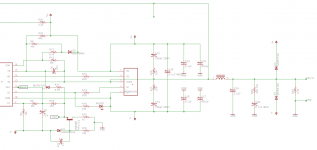
I attach photos of the pcd, and the schematic I have used. It should be the same as the one in IRAUDAMP7S rev1.0 but different LPF component values.
Two dual power supplies are being used (each one with outputs at 25V) to have +/-50V in power rails.
Mosfets and driver are always cool, so it seems to be a problem with decoupling. But Im not sure what to do....
It might help but in stanby circuit draws about 10-20mA from the power supply.
I attach photos of the pcd, and the schematic I have used. It should be the same as the one in IRAUDAMP7S rev1.0 but different LPF component values.
Attachments


Any advice on making a good pcb? Whats wrong?PCB Layout completely wrong ...
A Class D amplifier requires a much better PCB Layout.
The easiest way is to use a pcb layout and circuit designed by IR.
There are some in the data sheets.
It took me a few revisions before I got a pcb to work, even then I had to scale back the voltages for over current to get it to work loud enough.
Decoupling is vital as close to the mosfets and IC as possible.
Tracks need to be as thick and as short as possible.
There are some in the data sheets.
It took me a few revisions before I got a pcb to work, even then I had to scale back the voltages for over current to get it to work loud enough.
Decoupling is vital as close to the mosfets and IC as possible.
Tracks need to be as thick and as short as possible.
- Status
- This old topic is closed. If you want to reopen this topic, contact a moderator using the "Report Post" button.
- Home
- Amplifiers
- Class D
- IRS2092 shorts when connecting IRHI2019H