Hi,
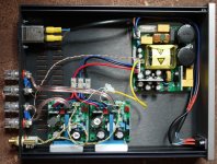
I have just got a SMPS400A180 and 2x UcD180HG/HxR but I'm not 100% sure how I'm supposed to connect the DC error, Auto Amplifier Enable, Amplifier Standby or SMPS Standby connections.
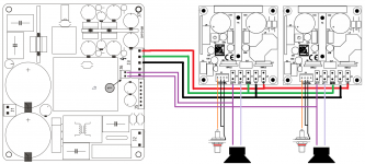
I've attached a diagram. Is the DC Error Input done correctly? It just connects to LS+?
Also, what am I supposed to do with Auto Amplifier Enable, SMPS Standby or Amplifier Standby? I will just be using a switch on the mains input to the SMPS400.
Any help appreciated!
I have just got a SMPS400A180 and 2x UcD180HG/HxR but I'm not 100% sure how I'm supposed to connect the DC error, Auto Amplifier Enable, Amplifier Standby or SMPS Standby connections.
I've attached a diagram. Is the DC Error Input done correctly? It just connects to LS+?
Also, what am I supposed to do with Auto Amplifier Enable, SMPS Standby or Amplifier Standby? I will just be using a switch on the mains input to the SMPS400.
Any help appreciated!
Attachments
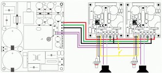
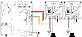
Just updating this thread with how I wired the "auto amplifier enable" connections between the SMPS400 and UCD180s. This way the PSU triggers the amp modules to turn on. I don't think it makes a lot of difference but perhaps if the PSU were to have an internal fault it would stop the AMP modules powering up.
Attachments
Just updating this thread with how I wired the "auto amplifier enable" connections between the SMPS400 and UCD180s. This way the PSU triggers the amp modules to turn on. I don't think it makes a lot of difference but perhaps if the PSU were to have an internal fault it would stop the AMP modules powering up.
Thank's for this wiring diagram.. It helped me a lot ! I'm still trying to figure out if there is some kind of auto shutoff / standby mode and how to activate it.
Greetings
Hi,
By any chance could someone help me out with my UCD400 and SMPS400.
I'm sure I have made a really simple mistake, but I just can't see it.
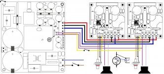
I have wired these two boards together using the attached wiring diagram.
When powered up the HxRs glow red, so they are getting power.
When I close the switch between J3: pin 5 of the SMPS400 and J4 on the UCD400, the blue LED on the UCD400 lights up.
But for some reason the UCD400 itself is playing audio?
Any suggestions?
Thank you.
Ste
By any chance could someone help me out with my UCD400 and SMPS400.
I'm sure I have made a really simple mistake, but I just can't see it.
I have wired these two boards together using the attached wiring diagram.
When powered up the HxRs glow red, so they are getting power.
When I close the switch between J3: pin 5 of the SMPS400 and J4 on the UCD400, the blue LED on the UCD400 lights up.
But for some reason the UCD400 itself is playing audio?
Any suggestions?
Thank you.
Ste
Attachments
Hi,
Thanks for your reply and encouragement...
I'll keep scratching the ole nogging, stare at it for a while longer and see if I can find the problem and let you all know for future diy-ers.
Probably a loose crimp connection or something.
Done a lot of continuity testing with my DMM but i'll keep working on it")
Thanks again.
Thanks for your reply and encouragement...
I'll keep scratching the ole nogging, stare at it for a while longer and see if I can find the problem and let you all know for future diy-ers.
Probably a loose crimp connection or something.
Done a lot of continuity testing with my DMM but i'll keep working on it
Thanks again.
Sorry my bad, must have forgot that bit.
Despite seeing that blue LED light up.... I can hear that the UCD module itself is still playing the audio . and either no sound, or very very quiet signal out of LS+ and LS-
But I thought the blue LED the indicator it was done.
Any suggestions welcome... I'm gna keep going at it and will keep everyone posted
Hi all, i think the chaps over at Hypex have found the solution.
They just suggested I may have accidentally shorted the speaker outputs through the chassis.
And I remember drilling the holes in the chassis for the banana plug terminal posts, it was quite snug... so I think that must be it
Just going into work at the moment, will see if that's the problem either tonight or tomorrow morning and keep yaz posted.. thanks for everyone's input.
Ste
They just suggested I may have accidentally shorted the speaker outputs through the chassis.
And I remember drilling the holes in the chassis for the banana plug terminal posts, it was quite snug... so I think that must be it
Just going into work at the moment, will see if that's the problem either tonight or tomorrow morning and keep yaz posted
.. thanks for everyone's input.Ste
- Status
- This old topic is closed. If you want to reopen this topic, contact a moderator using the "Report Post" button.
- Home
- Amplifiers
- Class D
- Hypex SMPS400 + 2x UCD180 wiring (DC error, Auto Amplifier Enable, Amplifier Standby)