Headroom for JLH, Tringlophone, TA2020, TA2024, spirited playback with less clipping.
ClipNipper is a simple passive on-demand (doesn't activate until needed) compressor (booster like the Volumax) that doesn't consume your battery power and it doesn't reduce useful output power, but what you get is a headroom boost. This device mitigates/reduces clipping but it will not block everything and thus it doesn't reduce your bass. It will mimic the headroom advantage of a good tube amp.
This schematic is currently up to date.
(log in to see schematic)
Notes ----------------------------------------------------------------------------------------------
Input:
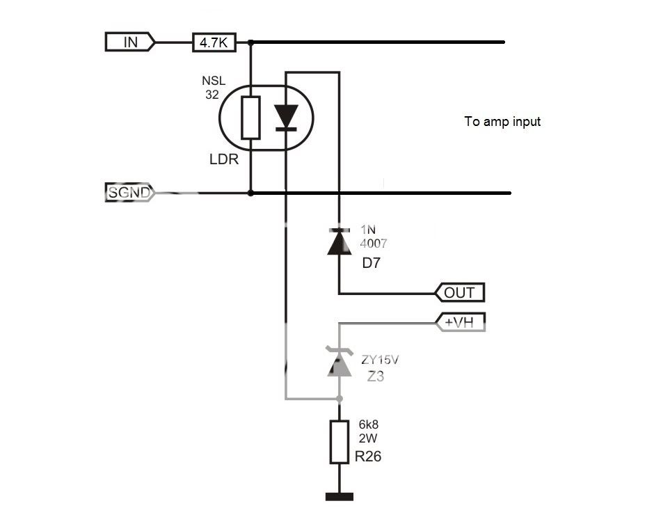
As shown in the schematic above, the location of this fixed divider and its function is just like an ordinary 20k volume control turned almost all the way up. . . except for momentary LDR activations that constrain clipping.
Series resistance at input is within the range of 330 ohms to 1K whereby the larger value allows more volume fluctuation--set this to personal taste. I like 820R. Some optional gain management documentation is at post 17.
Substitutions:
3.1v Led: The 20ma+ 3.1v LED can be a white, Warm White, Green, Blue, Pink, or Purple LED.
2v Led: The 20ma+ 2v led in red, yellow, amber, orange can be used as four leds series plus two ordinary diodes series like (4*2v=8v)+(2*0.7v=1.4v)=9.4v total forward voltage drop, but I didn't test that--see settings/tuning below.
Schottky: You can use almost any Schottky or fast diode you happen to have instead of the Schottky diodes in my schematics.
Rectifier: The bridge rectifier doesn't have to be made of 1n4007. A miniature prefabricated bridge rectifier would work nicely too--the ~~ AC marks are for the speaker jack, but the +- marks run the ClipNipper's LED's.
Settings/tuning:
It takes a bit of fine tuning, so have extra schottky (or fast silicon diodes) handy for that. If you need to trim a larger step, an amber or red LED is about 2v. More or less diode voltage drops in series to the LDR (led section) is how you set it. You'll have to try a variety of tracks before arriving at the setting that works best on average for your amplifier.
Stereo:
CDS LDR's never match, but that isn't difficult. To get the LDR's to work most easily, build atop a 20k volume pot with the LDRs from wiper to ground and from 820R to 1K series resistors at input (or just turn the pot dial slightly off of max if you intend to replace the pot with equivalent resistors later). With the LDR's off then parallel the weakest with a resistor to make the channels match. Parallel with the LDR's is also a decent spot for a picofareds cap if the circuit is used in radio production environment. And with the LDR's On adjust the detector's bias resistor (and/or add series resistance to the strongest LDR) to make the channels match. Lastly, you can substitute the 20k pot for equivalent resistors, if desired, or you can keep the pot as a volume control that refuses to clip (if you add resistors to the input of the pot). For stereo, the matching up seems like a slight bother, but it is quite fast to do since the pot has already conquered most of the variance.
LDR Optocoupler:
It is important to find an LDR that can pull down to 1K, but if this can't be found, then it is possible to put several (of the resistor sections) in parallel. The problem with an LDR that only pulls down to 10K is that you'd have to set it to engage much too early, and we wouldn't want to do that.
DIY CDS Optocoupler:
If there's not an LDR optocoupler handy, you can make one so easily. Just file the top of a white LED flat, then glue it to a CDS cell with clear glue, tape over the wires and paint that thing black. After it dries and after tape removal, you've got a DIY LDR optocoupler. 🙂
Battery management parts:
As a caveat of of its Zero standby drain design, ClipNipper will not reliably retard clipping for battery powered units with run down batteries unless the amp is run from a boost (or buck boost) type regulator. Eva's post #13 is a great idea for battery powered amp, but I couldn't figure out how to make that type of sensor work for bridge amp.
Larger scale amplifier applications:
Actually 3 LED's isn't enough for a larger scale amplifier, so for using ClipNipper to scrape the screech off of an LM3886 or even give the clean LM1875's a boost, you could start by simply adding more LED's and possibly a small change the drainer resistor value as needed for appropriate LED current. ClipNipper can be powered by a preamplifier, which may be both more convenient and more durable than adding it directly to a big power amp (see the datasheet for led max current figure). If one needs greater abruptness, one could use combination of zener and led instead of all led. Not all amplifiers/applications are equally dynamic. To track good dynamics without squashing, use more led, but to track lesser dynamics plus firmer control, employ some abrupt zener. Balance this out to track with your application and simply aim for pretty (pretty is better than clipping).
ClipNipper does not contain peak protection but can reduce the duration of overload conditions by turning down the volume. The ClipNipper is interoperable with other limiters and soft clippers as well (see Cordell's KleverKlipper)--simply adjust the ClipNipper compressor to engage first. And, that can be useful with the chip based amplifiers, to approximately hold the frequency response level instead of listening to a chip amplifier's inbuilt limiter.
Update:
At post 58, Elvee has modified the ClipNipper to support Class A Tringlophone.
Update:
Good place to buy LDR's: http://www.buildanamp.com/2-Light-Dependent-Resistors-LDRs_c2.htm
ClipNipper is a simple passive on-demand (doesn't activate until needed) compressor (booster like the Volumax) that doesn't consume your battery power and it doesn't reduce useful output power, but what you get is a headroom boost. This device mitigates/reduces clipping but it will not block everything and thus it doesn't reduce your bass. It will mimic the headroom advantage of a good tube amp.
This schematic is currently up to date.
(log in to see schematic)
Notes ----------------------------------------------------------------------------------------------
Input:
As shown in the schematic above, the location of this fixed divider and its function is just like an ordinary 20k volume control turned almost all the way up. . . except for momentary LDR activations that constrain clipping.
Series resistance at input is within the range of 330 ohms to 1K whereby the larger value allows more volume fluctuation--set this to personal taste. I like 820R. Some optional gain management documentation is at post 17.
Substitutions:
3.1v Led: The 20ma+ 3.1v LED can be a white, Warm White, Green, Blue, Pink, or Purple LED.
2v Led: The 20ma+ 2v led in red, yellow, amber, orange can be used as four leds series plus two ordinary diodes series like (4*2v=8v)+(2*0.7v=1.4v)=9.4v total forward voltage drop, but I didn't test that--see settings/tuning below.
Schottky: You can use almost any Schottky or fast diode you happen to have instead of the Schottky diodes in my schematics.
Rectifier: The bridge rectifier doesn't have to be made of 1n4007. A miniature prefabricated bridge rectifier would work nicely too--the ~~ AC marks are for the speaker jack, but the +- marks run the ClipNipper's LED's.
Settings/tuning:
It takes a bit of fine tuning, so have extra schottky (or fast silicon diodes) handy for that. If you need to trim a larger step, an amber or red LED is about 2v. More or less diode voltage drops in series to the LDR (led section) is how you set it. You'll have to try a variety of tracks before arriving at the setting that works best on average for your amplifier.
Stereo:
CDS LDR's never match, but that isn't difficult. To get the LDR's to work most easily, build atop a 20k volume pot with the LDRs from wiper to ground and from 820R to 1K series resistors at input (or just turn the pot dial slightly off of max if you intend to replace the pot with equivalent resistors later). With the LDR's off then parallel the weakest with a resistor to make the channels match. Parallel with the LDR's is also a decent spot for a picofareds cap if the circuit is used in radio production environment. And with the LDR's On adjust the detector's bias resistor (and/or add series resistance to the strongest LDR) to make the channels match. Lastly, you can substitute the 20k pot for equivalent resistors, if desired, or you can keep the pot as a volume control that refuses to clip (if you add resistors to the input of the pot). For stereo, the matching up seems like a slight bother, but it is quite fast to do since the pot has already conquered most of the variance.
LDR Optocoupler:
It is important to find an LDR that can pull down to 1K, but if this can't be found, then it is possible to put several (of the resistor sections) in parallel. The problem with an LDR that only pulls down to 10K is that you'd have to set it to engage much too early, and we wouldn't want to do that.
DIY CDS Optocoupler:
If there's not an LDR optocoupler handy, you can make one so easily. Just file the top of a white LED flat, then glue it to a CDS cell with clear glue, tape over the wires and paint that thing black. After it dries and after tape removal, you've got a DIY LDR optocoupler. 🙂
Battery management parts:
As a caveat of of its Zero standby drain design, ClipNipper will not reliably retard clipping for battery powered units with run down batteries unless the amp is run from a boost (or buck boost) type regulator. Eva's post #13 is a great idea for battery powered amp, but I couldn't figure out how to make that type of sensor work for bridge amp.
Larger scale amplifier applications:
Actually 3 LED's isn't enough for a larger scale amplifier, so for using ClipNipper to scrape the screech off of an LM3886 or even give the clean LM1875's a boost, you could start by simply adding more LED's and possibly a small change the drainer resistor value as needed for appropriate LED current. ClipNipper can be powered by a preamplifier, which may be both more convenient and more durable than adding it directly to a big power amp (see the datasheet for led max current figure). If one needs greater abruptness, one could use combination of zener and led instead of all led. Not all amplifiers/applications are equally dynamic. To track good dynamics without squashing, use more led, but to track lesser dynamics plus firmer control, employ some abrupt zener. Balance this out to track with your application and simply aim for pretty (pretty is better than clipping).
ClipNipper does not contain peak protection but can reduce the duration of overload conditions by turning down the volume. The ClipNipper is interoperable with other limiters and soft clippers as well (see Cordell's KleverKlipper)--simply adjust the ClipNipper compressor to engage first. And, that can be useful with the chip based amplifiers, to approximately hold the frequency response level instead of listening to a chip amplifier's inbuilt limiter.
Update:
At post 58, Elvee has modified the ClipNipper to support Class A Tringlophone.
Update:
Good place to buy LDR's: http://www.buildanamp.com/2-Light-Dependent-Resistors-LDRs_c2.htm
Last edited:
You could use a bridge rectifier to process positive and negative peaks with the same LDR LED. 270 Ohms is very low for the series resistor. Was that a typo?
You could use a bridge rectifier to process positive and negative peaks with the same LDR LED. 270 Ohms is very low for the series resistor. Was that a typo?
That input location looks like a 20k pot turned almost all the way up and it really is: In the real sample, I wired ClipNipper's CDS cell between the center and ground of this potentiometer: Cheap Tripath TA2020 When I checked it after jammin out, the series loss of the potentiometer's input side was set at 280R.
I have replaced that potentiometer with fixed resistors, since input loss is not pretty and since, conveniently, my sources have their own volume controls.
Thank you for the message. I have adjusted post1 for slightly higher resistor values per durability concerns. It is possible that somebody may push the input with the preamp or an old CD player. It is possible that somebody may push the sensor with Sure's more aggressive TA2024.
Sensor:
The speaker jack sensor part of circuit looks exactly like an LED's in Series schematic, R>>>>> except that at least one of the diodes is a power diode and one of the diodes is an LDR optocoupler.
And, yes it does run half wave because there is less voltage to waste into the resistor and because LED tolerate more peak than constant, thus the peaks of half wave allow safer operation over a wider voltage range.
My sample looks like 330R, 3.1v, 3.1v, 0.3v, ~2v, 0.34v; however, the change to 390R resistor drain is not a problem.
Last edited:
Abrupt didn't work well.
To go lower and thus more abrupt, you'd add more LDR's--with my LDR's two of them would 1k//1k=500R. Other way for more abruptness, is to hook one LDR into the gain setting instead. Personally, I don't want any of that because abrupt is less useful to audio quality. . . in my system.
Possibly, increasing abruptness is something you'd want to explore if your particular LDR's couldn't get lower than 2k.
With ordinary CDS cells (DIY LDR optocouplers), possibly paralleling a few of them could help level out component variances.
I don't know why you want the voltage boost. A full wave signal into the sensor would be more abrupt, yet still max out similarly albeit sooner. The effectiveness caveat of an LDR optocoupler's CDS section is because they can't short. Mine has a low limit of 1k and pushing the inbuild LED harder won't change that.You could use a bridge rectifier. . .
To go lower and thus more abrupt, you'd add more LDR's--with my LDR's two of them would 1k//1k=500R. Other way for more abruptness, is to hook one LDR into the gain setting instead. Personally, I don't want any of that because abrupt is less useful to audio quality. . . in my system.
Possibly, increasing abruptness is something you'd want to explore if your particular LDR's couldn't get lower than 2k.
With ordinary CDS cells (DIY LDR optocouplers), possibly paralleling a few of them could help level out component variances.
There are similarities but the application is different--big amp or small amp.you concept sounds similar to this:
Audio Amp Power Limiter
Rod Elliot's compressor automatic volume control circuit would give you less bass from a low powered amplifier. My ClipNipper (a soft clip device) does give you maximum bass but you'll need to operate your own volume control manually, since it doesn't give you effective automatic volume control and therefore cannot protect itself from a high powered amplifier.
Actually you can fine tune a prosound type compressor automatic volume control to work with a small scale amplifier, but a thoroughly effective automatic volume control for T-amp would need either split rail operation or an active buffered automatic volume control. Locating a large series loss in-between speaker jack and input cap was not acceptable with my TA2020.
You can do input losses as "the exception instead of the rule" if you had the "backwards" CDS that go to 330 ohms or less in the dark and then get much bigger values when lit up. This could be put series to the input of a T-amp without the audio quality problems of large series losses, since the large loss can't happen except during clipping prevention. In this case the easy ClipNipper sensor and/or Rod Elliot's example can be used. Too much light on the non-shunting LDR will disconnect the input, so it will need a paralleled resistor to prevent popping sounds.
330 Ohms is still very low for the input resistor. There are 2 problems:I have adjusted post1 for slightly higher resistor values....
A) If the amp is driven from a source with a low output impedance, then very little attenuation is possible. With maximum current through the LED, the LDR resistance only drops to 1 K. That gives less than 3dB attenuation with a 330 Ohm series resistor.
B) When the limiter is active, the input impedance is very low. this makes it difficult for the source component to drive.
IMO, 4.7K would be more appropriate for the series resistor. That ensures that the input impedance is never less than 5K, and also allows a more useful control range for the limiter.
The problem with half wave detection is that some musical waveforms are unsymmetrical, with very different amplitudes for the positive and negative peaks.And, yes it does run half wave....
If you sense only the positive peaks and the music has large negative peaks, then the amplifier may clip badly without your sensor noticing.
Last edited:
Turn my soft clipper limiter into a regular limiter? Okay.330 Ohms is still very low for the input resistor. There are 2 problems:
A) If the amp is driven from a source with a low output impedance, then very little attenuation is possible. With maximum current through the LED, the LDR resistance only drops to 1 K. That gives less than 3dB attenuation with a 330 Ohm series resistor.
B) When the limiter is active, the input impedance is very low. this makes it difficult for the source component to drive.
The problem with half wave detection is that some musical waveforms are unsymmetrical, with very different amplitudes for the positive and negative peaks. If you sense only the positive peaks and the music has large negative peaks, then the amplifier may clip badly without your sensor noticing.
Input Control:
1k input loss (more than that will make bad limiter pulsing noise)
22k input load parallel with the LDR's onboard CDS
During clipping this is a "more than half" voltage divider.
Substitutes:
820R input loss will decrease limiter pulsing noises and that is also acceptable for the soft clipper limiter at post 1.
Speaker output Sensor:
1N4007 Full Wave bridge rectifier.
Sensor is these (components in series just like LED's in series):
5.6v Zener, 3.1v LED, 470 ohm resistor, LDR's LED, 1n914
A 22uF cap is parallel to just the LDR's onboard LED.
Substitutes:
If 3.1v led and/or 5.6v zener aren't handy, you can substitute an equivalent amount of LEDs, Zeners or ordinary diodes that add up to the desired voltage drop(s).
Advantages of this version: Better quality treble. More protective. It doesn't "miss" You are correct.
Disadvantages of this version: Somewhat less bass, and it "sounds like a limiter" as in less transparent.
The disadvantages were expected, but I minimized them.
Advantages of both versions: A noise reducer that is powered only by noise. No added standby consumption. BlareBuster compatible. You can play a tiny amplifier louder than heck without clipping noise.
P.S.
This amp TA2020 20W Class-T Digital Audio Amp wasn't as cheap as I thought since it does contain the 8 protection diodes on the bottom, it does contain the four upgraded inductors at the output, and it has a 3A schottky series to the power so as to seriously drop voltage during overcurrent condition. A Low ESR capacitor upgrade is useful for it. But, if it wasn't for harsh operating conditions in an old, yet solar powered RV, I would be using a different amplifier.
Last edited:
Thanks!
Okay I re-did the Full Wave type sensor for a bit louder bass.
Full wave bridge rectifier at speaker jack running:
1n5819, 3.1v LED, 3.1v LED, 3.1v LED, 390 Ohm resistor, LDR's LED
22uF cap paralleled directly to only the LDR's LED.
The ~3.1v led are InGan White or warm white LED that stumble across their knee voltage (better bass than the fast attack of zener). You'll get quite the light show. The resistor drain can be 390R to 470R. You can add more or less 1n5819 (schottky) to fine tune.
Ooh, an actual limiter that really rocks. Thanks Godfrey!
Last edited:
Schematics
Thank you for the schematic. I have revised it. See the attachments.
Input:
We need an input load resistor because the 1k to 50k LDR optocoupler could (varies) go nearly open circuit when off.
Sensor:
We need to set the sensor's voltage range suited to TA2020, TA2024,
We need to do without a ground tap for sensor (bridge amp doesn't have an output ground),
We need to set the sensor so that the amplifier plays louder and still clean (unusual for a limiter)
Noises:
We need to reduce the effectiveness of the limiter enough to remove obvious pulsing noises,
We need to reduce the effectiveness of the limiter enough so that we don't require high gain/preamplifier noise.
Frequency Response:
We need to use LED and Schottky voltage drops because their sloppy knee voltage region will make a more transparent rendering and LOUDER BASS than abrupt zener.
Please check the attached schematics for polarity. I did test these actual components with the real amp. A 3.1v LED is an ordinary white or warmwhite LED ("on" voltage varies by current). You can fine tune voltage drop to match your amp by either subtracting 1 schottky diode or adding more schottky/fast silicon diodes.
Attachments


Last edited:
My recommendation: Sense a too low voltage drop from one output to the positive rail or to ground rather than just a too high output voltage. Why? To allow for any supply voltage and sag.
Nice idea otherwise.
Nice idea otherwise.
hi daniel,some friend of mine say that at high frequency the LDR will be less responsive,because LDR has 200-500us response time
Thank you!My recommendation: Sense a too low voltage drop from one output to the positive rail or to ground rather than just a too high output voltage. Why? To allow for any supply voltage and sag.
Nice idea otherwise.
I couldn't quite figure out how to do that type of sensor with a bridge amp and still make it play louder instead of quieter.
You can try 4n25 instead of LDR for soft clipper -or- try the full wave version of ClipNipper since that a mild limiter with a nice smooth treble response.hi daniel,some friend of mine say that at high frequency the LDR will be less responsive,because LDR has 200-500us response time
Gain management documentation
The Easy way--For higher gain, you could set RI (Tripath datasheet RI resistors are located "chip side" of the input cap) to 10k (instead of datasheet 22k) for a "gain mod" boost of replacing 2 SMD resistors with two ordinary resistors. I used this method personally, on the real TA2020 amplifier. It was easy on that amp. I also needed a thick (good quality) shielded input cable, which is a normal requirement for TA2020.
-or-
Modest/slight difficulty--Changing the schematic's input resistor to lower figure, like 470R instead of 1k, and also increase 22k input load resistor on the schematic up to 33k as these steps are just like turning up a volume knob's proportions. You don't want excess at all, but you do have the freedom to adjust this spot. If your weakest source still can't light up the LED's then either replace the amp gain SMD resistors or give a weak source its own preamplifier.
-or-
Extra complicated--You can automate a Lightspeed Attenuator by powering it from my sensor that is on the schematic. This prospect can reduce the input loss except for when the sensor is lit up. Since LED's don't directly parallel, a Lightspeed Attenuator uses two private voltage drop sections and TWO private drainer resistors but may be powered from just one bridge rectifier.
-or-
Zero loss method (auto gain ride)--Instead of LDR optocouplers at the input, the very first edition of ClipNipper did nip parallel to the gain settings (inert except for removing clipping) on a discrete amp, but I avoided it this time because there isn't board space available except for amplifier re-design.
Question answered, Studio compression/clipped recordings, make audible pulsing.
Modern InGan LED retrofit lighting bulbs will burn down an RV that has a half wave converter because of 13.5vdc AND ~6.5vac, but most InGan see the total sum of ~20v or more. Since clipping has similarities to dirty DC, most InGan react extra strongly to clipped audio signals. It makes a great detector that sometimes works too well.
It can be used for detecting clipping and blare, but it could also detect static/fuzz via exacerbator op amp active detector. Then we have ldr, cds, optotransistor and solid state switching technologies for which to apply feedback and thus cancel any of those noises.
I can't do anything about ClipNipper overreacting to music that was recorded hot with clipping and compression, except. . .
I will soon be attempting to integrate the BlareBuster at the input to ClipNipper and automate the engagement points by using the new detector. By removing a small amount of studio compression first, then ClipNipper can be free to work more accurately, without the noticeable pulsing that sometimes occurs on highly compressed tracks. It can be done with 4 or 5 passive parts per channel and not consume battery power. Zero energy consumption simple design won't remove clipping at low volume playback. The stand-alone prototypes are complete, interoperable and producing results. Integration and automation remains to be completed. Now that we can play loud, the next logical step is the BlareBuster, because "can play loud" and "want to play loud" are two different things.
There won't be any attention getting theater like effects--the effectiveness will be decreased as much as necessary to achieve transparency, because of the belief that noise removers must not add noise.
P.S.
Since I'm not a formally educated audio engineer, but rather more like going through Edison's 1000 ways of not making a light bulb, expect another delay since that process is slow and then expect another "steam punk like" simple circuit already working and running, before a schematic is published. 😀
Sorry for the delay in redeploying the hi-fi uncompressor to fit T-amp.
Last edited:
Here's a radical idea: use the clipping (overload) pin on the amp chip to do something. Whoever lays out those boards deserves a kick to a delicate part of the body for not bringing that pin out to a terminal, preferably through a buffer to drive an LED.
If you can drive an LED, you can drive an LDR or a 4n25, which both do contain leds. But, I don't know if their onboard detector is abrupt or variable or slow or fast. Have you tried it?Here's a radical idea: use the clipping (overload) pin on the amp chip to do something. Whoever lays out those boards deserves a kick to a delicate part of the body for not bringing that pin out to a terminal, preferably through a buffer to drive an LED.
- Status
- Not open for further replies.
- Home
- Amplifiers
- Class D
- LDR Limiter for TA2020, TA2024, spirited playback without clipping.