Okay I re-did the Full Wave type sensor for a bit louder bass.
Full wave bridge rectifier at speaker jack running:
1n5819, 3.1v LED, 3.1v LED, 3.1v LED, 390 Ohm resistor, LDR's LED
22uF cap paralleled directly to only the LDR's LED.
The ~3.1v led are InGan White or warm white LED that stumble across their knee voltage (better bass than the fast attack of zener). You'll get quite the light show. The resistor drain can be 390R to 470R. You can add more or less 1n5819 (schottky) to fine tune.
Ooh, an actual limiter that really rocks. Thanks Godfrey!
Is this reflected in the schematic of post #1?
Mac
That version is the schematic at the top of post 1.
That's the rowdy volumax like boost (really rocks) for TA2020
I have changed only one thing since that publication--I'm now using an MR fast silicon diode instead of the 1n5819.
P.S.
Elvee's more refined version is explained at post 58.
Amplifiers and LDR's are all different, so choose whichever schematic you like best.
It is easy to try both versions, since the parts difference is a cap and a resistor.
Last edited:
That version is the schematic at the top of post 1.
That's the rowdy volumax like boost (really rocks) for TA2020
I have changed only one thing since that publication--I'm now using an MR fast silicon diode instead of the 1n5819.
P.S.
Elvee's more refined version is explained at post 58.
Amplifiers and LDR's are all different, so choose whichever schematic you like best.
It is easy to try both versions, since the parts difference is a cap and a resistor.
Ok, thanks a lot.

New information added:
Some high performance optocouplers resistance goes to almost short (high dynamic range); however, the opto used in the schematic at the top of post1 didn't have that capacity. To adjust, you might want to employ a 1k trimmer as a variable resistor placed in series with the optocoupler's resistance.
Some high performance optocouplers resistance goes to almost short (high dynamic range); however, the opto used in the schematic at the top of post1 didn't have that capacity. To adjust, you might want to employ a 1k trimmer as a variable resistor placed in series with the optocoupler's resistance.
Daniel
I like your idea. Its to easy to not try... if I played music really loud. 96db speakers mean I dont clip.
So one question and one suggestion.
What LDRs go to almost a short? I get about 40 ohms on NSL32SR2 as you know.
There are other optocouplers that work just like a resistor. Meaning that signal can flow both ways without being turned to DC like a lot of transistor based optocouplers. CPC1017 and a lot of others by Clare/IXYS are super cool little guys that have back to back mosfets and let me guarantee you they sound great. When I use them they have between 4 and 7 ohms resistance.
What I was thinking is that you could have three filters on the input going to ground. You have a treble/bass/midbass filters. Each filter employs a CPC1017 instead of a LDR. At the output you have the same filters. Now you only clip the offending frequency range.
Yeah its more complicated and your original already gets the job done but everyone else got to have their say and I felt left out!")
Really I just wanted to commend you on your cool circuit and share that CPC1017. I highly recommend using it in the signal whenever you feel like you need an on/off switch. They are cheap and totally transparent with no distortion that my AP can see.
Uriah
I like your idea. Its to easy to not try... if I played music really loud. 96db speakers mean I dont clip.
So one question and one suggestion.
What LDRs go to almost a short? I get about 40 ohms on NSL32SR2 as you know.
There are other optocouplers that work just like a resistor. Meaning that signal can flow both ways without being turned to DC like a lot of transistor based optocouplers. CPC1017 and a lot of others by Clare/IXYS are super cool little guys that have back to back mosfets and let me guarantee you they sound great. When I use them they have between 4 and 7 ohms resistance.
What I was thinking is that you could have three filters on the input going to ground. You have a treble/bass/midbass filters. Each filter employs a CPC1017 instead of a LDR. At the output you have the same filters. Now you only clip the offending frequency range.
Yeah its more complicated and your original already gets the job done but everyone else got to have their say and I felt left out!
Really I just wanted to commend you on your cool circuit and share that CPC1017. I highly recommend using it in the signal whenever you feel like you need an on/off switch. They are cheap and totally transparent with no distortion that my AP can see.
Uriah
Thank you very much!Daniel
I like your idea. Its to easy to not try... if I played music really loud. 96db speakers mean I dont clip.
So one question and one suggestion.
What LDRs go to almost a short? I get about 40 ohms on NSL32SR2 as you know.
There are other optocouplers that work just like a resistor. Meaning that signal can flow both ways without being turned to DC like a lot of transistor based optocouplers. CPC1017 and a lot of others by Clare/IXYS are super cool little guys that have back to back mosfets and let me guarantee you they sound great. When I use them they have between 4 and 7 ohms resistance.
What I was thinking is that you could have three filters on the input going to ground. You have a treble/bass/midbass filters. Each filter employs a CPC1017 instead of a LDR. At the output you have the same filters. Now you only clip the offending frequency range.
Yeah its more complicated and your original already gets the job done but everyone else got to have their say and I felt left out!
Really I just wanted to commend you on your cool circuit and share that CPC1017. I highly recommend using it in the signal whenever you feel like you need an on/off switch. They are cheap and totally transparent with no distortion that my AP can see.
Uriah
The 40R is okay. Those will work. Did you try a clipnipper? Blow up the plaster?
Got schema??
I've been trying to imagine how to use a jfet as an on-demand variably resistive load instead of the optos, since all we're doing is fluctuating the input load at threshold and with delay cap. I wonder if there's a way to use the CPC1017 like that?
DA (dual asymmetric) option is finer than symmetric. This takes two units. There's just a half wave rectifier (one power diode, not four) and the circuit is otherwise similar. The second unit has the diodes flipped the other direction. Music is strongly asymmetric in nature, thus a Dual Asymmetric causes much less distortion, but at the cost of almost twice the parts count. This also solves the problem of weaker optos, since if the amp clipped badly, it would max out both of the optos in parallel to the input load.
I think that Future clipnippers and similar circuits should all be made dual asymmetric and not use any bridge rectifiers at the outputs of audio amplifiers.
Rockbox? Maybe you're sitting on it? Android. . .
This is an attempt to answer that question about frequencies versus compander. There's a few practicalities. It would be good to keep the bass naturally proportional to the midrange and treble, and that does not require a lot of contouring efforts. Recently, RockBox has been ported to Android as an application. And, that makes it easy to preview some of the options digitally.
Rasher's Rockbox related stuff - daily builds of Rockbox for Android
The 240x320, 320x480 and 480x800 files for phone and (scroll down farther) the 800x480 is useable for tablet.
For reference, music is normally located at ./sdcard/music on android.
For reference, you can set the font size within the rockbox software under settings-themesettings-font.
For reference, here's the compressor settings that are similar (but not quite as good as) the clipnipper:
Threshold = -6 (clipnipper's led string)
Makeup Gain = OFF (boost, yes, somewhere else)
Ratio = 2:1 (clipnipper's voltage divider)
Knee = Soft (led string's soft knees)
Attack Time = 15 ms (or more) (clipnipper's delay cap)
Release Time = 400 ms (clipnipper's delay cap)
Install rockbox first and then. . .
Here is a config file with settings and eq'ing, expander and compander already set up.
Right click (long touch), and "SAVE AS" (save link as)
http://startfetch.com/daniel/config.cfg
You can simply drop it into the ./sdcard/rockbox folder.
Disclaimer: Headphones recommended for that--little built in speakers in a smartphone might explode.
This not expensive! Newegg.com - sennheiser earbud
Sennheiser MX365 can be upgraded by using a paper punch on the foam pads to create "doughnut pads" and just put the factory perfect hole at the driver grille. Like most earbuds, they'll need a push for bass. Therefore the config file.
And the point: I am not familiar with any reason to put the frequency response out of proportion in a compressor, expander, or compander; however, there ARE some frequency response options in the RockBox software's compressor. Those are the ones that I assume might be applicable to audio.
I take it the clip nipper can be a little abrupt, but appropriately so and this is why you want a jfet to act as variable resistor which is just what they do. I think you could get an idea by reading the TI pdf on transconductance amps. Just a jfet from signal to ground with a pot from signal to the base might give you some of the effect you want. Or you could use a transconductance amp driven by a voltage divider on the output of your amp to power the ldr. Then you might get real smooth clip nipping.
Hey, these 50R~100K LDR's in your store look quite suitable!
LDRs Light Dependent Resistors Silonex NSL-32SR2
LDRs Light Dependent Resistors Silonex NSL-32SR2
Udailey, Feel free to produce the ClipNipper and/or preferably the higher performing ClipNipper DA (higher fidelity, twice as many optos, no bridge rectifiers) for nonprofit and/or profit use.
I have always been convinced that volume controls *should* result in effective concert sound if turned to max.
P.S.
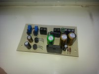
In other news, simple, dynamics promoting power supplies really do exist.
I have always been convinced that volume controls *should* result in effective concert sound if turned to max.
P.S.
In other news, simple, dynamics promoting power supplies really do exist.
Udailey, Feel free to produce the ClipNipper and/or preferably the higher performing ClipNipper DA (higher fidelity, twice as many optos, no bridge rectifiers) for nonprofit and/or profit use.
I have always been convinced that volume controls *should* result in effective concert sound if turned to max.
P.S.
In other news, simple, dynamics promoting power supplies really do exist.
Thanks for that offer Daniel. I have no idea if I will do that or not right now but its very generous of you.
Whats this power supply you are talking about?
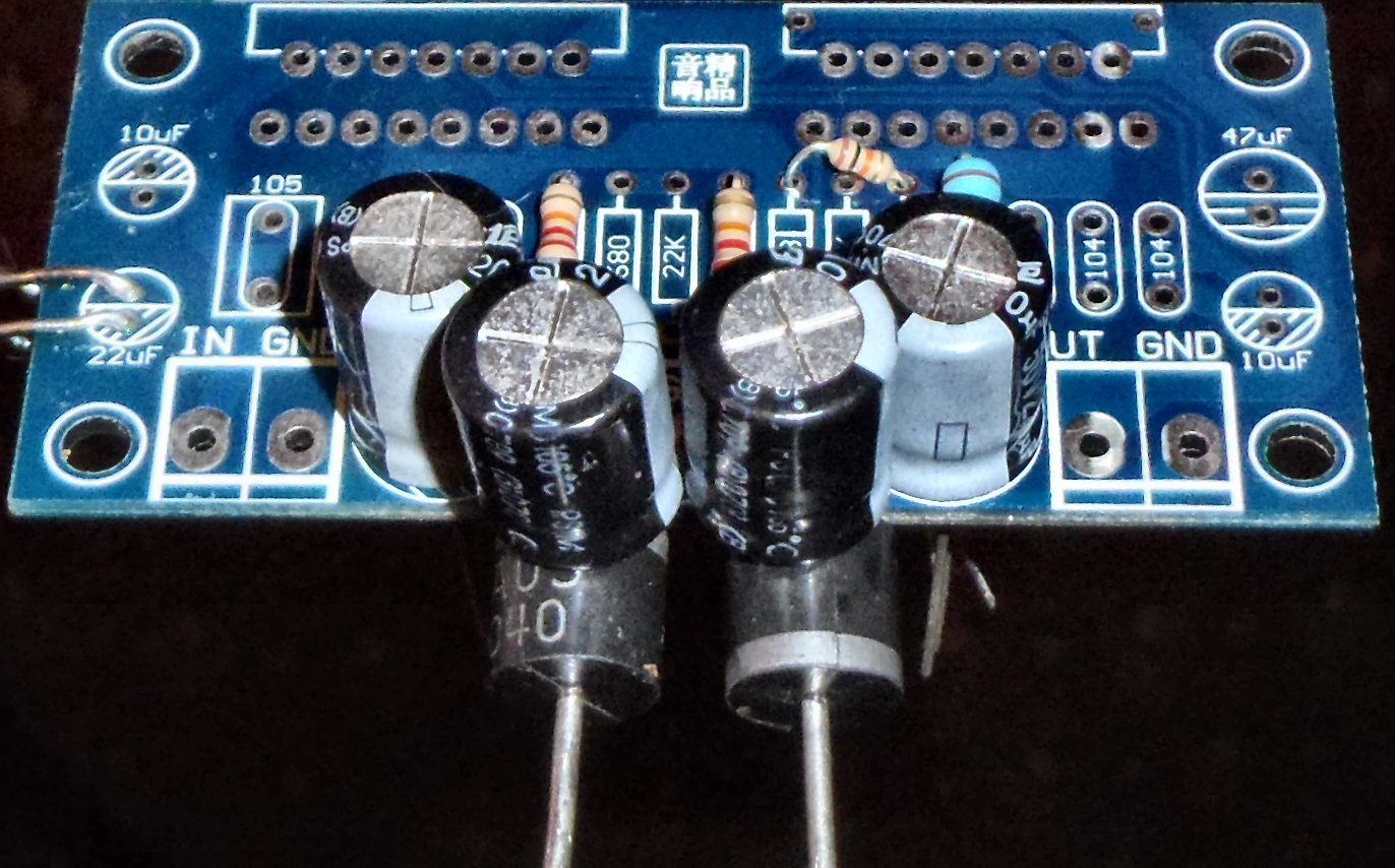
I have ordered 10 boards with two channels of noninverting LM3886 with the 1k noninverting input resistor replaced with an LDR and the inverting input to ground resistor (usually 680) replaced with an LDR. I wonder if you would like to have one of the boards? I was looking for a few people to assemble and test it. I think it would be pretty easy to also test it in bridged or parallel which is why I put two on one board, to mess around with different configurations. Of, course then we would have to add output resistors but thats not a big deal. Let me know with your address if you would like to try it. If it was to be commercial the two layers would be used to full advantage instead of mirroring my single layer design and the board would allow for better selection of parts in the zobel. Maybe single psu entry points rather than one for each amp. Other than that I'm pretty pleased with it.
Its not my intention to turn your thread to my advantage. This offer is for Danielwritesback only. Please dont pm me.
Uriah
Attachments
Thank you for your offer; however, the next round of LM3886/LM3876/LM3875/LM1876/LM4780 (any overture) will be inverting mode for me.
In regards to LDR as feedback-shunt-resistor, I have noticed that when I tried a Multi-Turn, CerMet, variable resistor, that it always worked better than an ordinary resistor--I have tried dialing in a just right value and then replacing the trimmer with same value fixed resistor, but the ordinary resistor Never works as well as the variable cermet, especially if they're the same value. When using an ordinary resistor instead, a given amp needs a little more gain, and that also means, a little more compensation. So, I end up leaving the cermet in-circuit.
As for power supplies, I did one for a good feature set despite a small 200VA transformer attempting 200W (statement speakers are 4 ohms). http://www.diyaudio.com/forums/chip-amps/226437-optimizing-tda7294-output-7.html#post3360423. Per rail, it looks like BR, 3300u, MBR1645||0.28R, 5x3300u. That is a low loss crc whereby a bypass diode prevents excessive filter losses (especially bass impact). The diode forward voltage drop figure sets the limit on crc filter losses, whereby schottky is about 0.3v, fast silicon is about 0.5v and standard silicon is about 0.7v (see forward voltage drop in a diode's datasheet). On my personal supply, I only allowed 0.3v for the CRC filter (my R is bypassed with MBR1645), and that is just fine because I have an additional filter. . .
And, next for the amplifier board Virtual Dual Mono which has ordinary 6A05 (6a1, 10a05, 10a1, sturdy standard silicon) diodes series with the V+ and V- power connection to each channel of audio amplifier board (that is a monophonic parallel amp in the photo--it takes 4 diodes for stereo + split rail, which is 2 diodes per each channel, as shown in the photo). The stereo width of virtual dual mono is not the main benefit, but it is a rather good excuse for doing it.
Just a quick note: decoupling cap size is specific to a given amplifier--A non-inverting LM3886 would require significantly larger power decoupling caps directly at the chip, but the prospects are otherwise similar.
We might disagree on using better parts for the zobel, because the standard and expected capacitor is a rather high esr polyester dip cap (like the little green tracon from the radio shack--this type filter cap looks like green or red blob); however, if a high efficiency, low loss, box cap were used then you'd need to increase your resistor value, else RC value comes out not known to be useful with audio amplifiers. SO, when it comes to the zobel, don't zoot the capz.
Last edited:
Oh, I had an idea! Since you've got an LDR for the feedback-shunt resistor, you could conceivably install a feedback resistor somewhere between 56k and 112k (much experimentation; but, somewhere in that range) and dial in a rather pretty tone with your LDR shunt, despite the tone difficulties with the non-inverting LM3886. I know the thing can image like a champ, however, practical tone often evades it. The adjustable variable control could be highly beneficial. Tone/Gain/Stability are very closely related and have a narrow range of perfect that is not usually hit on target by fixed resistor values.
The higher resistor values will also result in more audio being able to pass through the feedback coupling cap and thus less distortion.
P.S. I wonder why the LDR is more effective at base stopper locales?
I'm certainly not saying that it isn't, but rather, the fact that it is, is interesting.
The higher resistor values will also result in more audio being able to pass through the feedback coupling cap and thus less distortion.
P.S. I wonder why the LDR is more effective at base stopper locales?
I'm certainly not saying that it isn't, but rather, the fact that it is, is interesting.
Last edited:
HI...
i tried the limiter with the ldr but i can;t make it work...
i have less volume and when i turn the volume up the amp keeps cliping...
my ldr goes down to 800ohm with the led i used...
i did'n use extra bright led...
i added the limiter before the volume potensiometer...
what can i do to solve this problem?
It needs to be implemented like Daniel's schematic. If you dont have series resistance before it then it wont do a very good job. I also wonder the resistance range of the ldr you are using. What is its value when the circuit is off? It needs to be very high when off. Maybe 100k+. Assuming the ldr fits the bill I think your problem is positioning. Put it after the pot. Really this is the first thing you should do and it should have that ~1k resistor in series with signal right before it.
Last edited:
HI...
i tried the limiter with the ldr but i can;t make it work...
i have less volume and when i turn the volume up the amp keeps cliping...
my ldr goes down to 800ohm with the led i used...
i did'n use extra bright led...
i added the limiter before the volume potensiometer...
what can i do to solve this problem?
First, move the limiter to a position between the potentiometer and amplifier.
Secondly, observe the series LED's to find out when the engagement happens--they ought to turn on solid when the amp has reached max, but not before then.
If the LDR used is not reactive enough (I accidentally bought a few like that and those don't work at all), you'd need several in parallel to get enough loading action from them. Really unfortunate LDR's do exist.
It would be better to use only LDR's that are compatible with the LightSpeed Attenuator project. Each has a broad capacity that ranges from a few ohms to greater than 100k. That wide range is vital.
Last edited:
I know this thread is ancient, but it is still appreciated. Funny it should appear in the Class D forum, as I have in fact been looking to add a limiter like this, as the final piece of the puzzle, in a small battery powered Class-D practice guitar amplifier I've been working on for a long time. The final problem I encountered was that a guitar, by nature, has an extremely wide dynamic range, and as you may be aware, distortion caused by clipping in a class-D amplifier is neither pretty nor useful. The problem though is that if the amplifier is turned up to offer more volume when played quietly, it may be subject to some of this ugly distortion if the player starts strumming loud. The ideal solution would be a compressor/limiter, but as a simple practice amp, the added parts, costs, and controls needed for a complete "high-end" compressor circuit are just not justified. So, recently finding plenty of LDRs at places like electronicgoldmine, cheap even if not very well matched, I'm very hopeful I'll be able to concoct a simple and adequate LDR circuit like this.
Since I'll be dealing with a low power 20W class D amplifier, I'm a little concerned about driving the LDR directly from the loudspeaker, as I don't want to cause additional distortion at the point where the series zener starts conducting. But then maybe I'll get lucky and this won't be a problem.
Anyway, thanks for sharing this.
Last edited:
Well, it isn't 1927, so perhaps we ought to explore a little jfet.i like limiters but maybe put light bulb and led "in parallel" so there is some thermal memory.
Exploring a little jfet has been a goal, even though the 1970's LDR tech has been working well enough. The Achilles's heel of the LDR is repeat-ability when it comes to effectiveness. If the range isn't vast enough, then it will dull dynamics instead of working as expected. Yeah, they do make the right parts, but the shopping is a hazard!!!
- Status
- This old topic is closed. If you want to reopen this topic, contact a moderator using the "Report Post" button.
- Home
- Amplifiers
- Class D
- LDR Limiter for TA2020, TA2024, spirited playback without clipping.