Hard clipper and Soft clipper are different, because instead of shorting out the signal, we "trip" a voltage divider very quickly for a softer effect with no square corners.What do you mean by "soft"? I thought you meant "not abrupt", in a timing sense, as an abrupt clip will be crunchy.
Soft clipper (sensor is at amp input)--must be blazin fast. Function = cut the corners off the square
Limiter (sensor is at amp output)--must be slowed down via timer cap (makes great treble but there will be some bass disturbances if the amp is run three times more than its normal means).
All must be constrained so that their effects aren't obvious to the ear.
Transparent (polite, secret): The engagement point is completely ineffective. It is standby. At the point of engagement, the effect is so mild that it doesn't even work. As need increases, effect increases gently. Transparent = not obvious. Nebulous knee voltage of schottky and LED helps a lot.
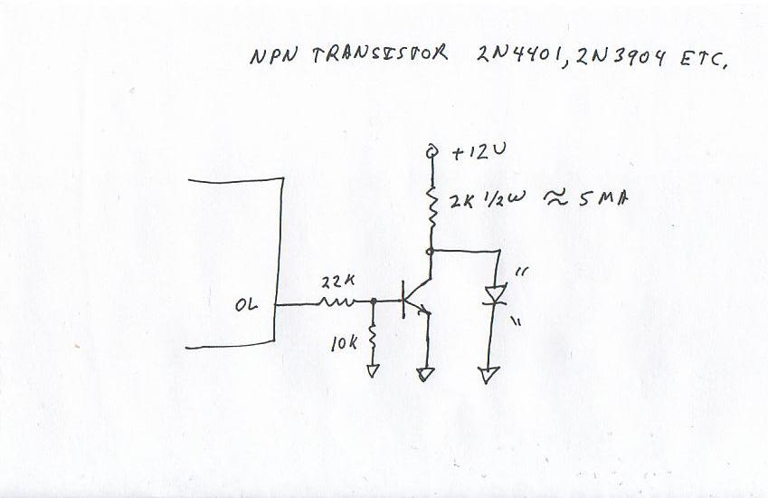
No cpu needed--InGan LED based detector lights brighter on dirty dc (clipping signal) but stays dim on ac (music). That feature is horribly dangerous for room lighting but works great for detector.
At some point of abusing the amplifier, transparency starts to fail, and in this case go for "pretty" since the option of increasing the power supply voltage doesn't work with the TA2020.
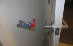
Abrupt (rude) = a Zener, or stepping on the garden rake. They're not soft, fluffy and sloppy. They're very noticeable. Specifically engineered for sudden engagement. They're not suitable. There's an abrupt device for bathroom doors and we should avoid this abrupt effect, since abrupt is not suitable--see attachment:
Attachments
Last edited:
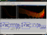
That's really cool. Did you build some?Another schematic. This illustrates the benefits of a high-order LP filter. High order harmonics are much lower. This is the result of an input voltage that is a combination of 500Hz and 490Hz, which produces a sine wave modulated at 10Hz, perfect for exploring limiter behavior.
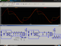
Wait, I didn't do that simulation right, try this one. I didn't equalize the levels...
Harmonics are higher before 650Hz, but this is because of the improved speed of the LP filter at low frequencies. The 1KHz intermodulation is lowered considerably with the better LP, which is the point. Better speed, as well as better filtering.
Harmonics are higher before 650Hz, but this is because of the improved speed of the LP filter at low frequencies. The 1KHz intermodulation is lowered considerably with the better LP, which is the point. Better speed, as well as better filtering.
Attachments
You're right, of course. I might be right too. Of course, Eva is right as well. It just depends on what frequencies you'd like to limit primarily.Arg, I keep contradicting myself. Let's see if I can get it right... Or if I'm even right at all...
The digital allows one to run multiple programs (multiple curve) on a single set of parts. When we use analog, that same feat requires multiple independent circuits--That is fast soft clipper with input side sensor run along with slow limiter with output side sensor. To limit the complexity, I hope we can do it in analog without making the analog circuit more complex than the digital circuit.
I think that since TA2020 clips badly well before its datasheet claims then ear sensitivity 1k~8k need to be limited primarily. I think it takes added circuits to either clean up or constrain the rest.
I'd like to see what you can do with 4n25 and dropping the internal led voltage to avoid heat. I used additional led's for that but you can use whatever you like although I do suggest at least one added led and at least one added 1N5819 (high voltage low amperage fast silicon diode or a similar Rectifier schottky) set in series to the 4n25's internal led.
We could have input monitor as a small op-amp driving the 4n25, and in this case, the output of the op-amp is not used for music--we can clip the op-amp, not the power amp.
") I'd also like to see a convenient dial for fine tuning extent (amplitude of the automated voltage divider) and another dial for fine tuning engagement (voltage to light the 4n25).
I'd also like to see a convenient dial for fine tuning extent (amplitude of the automated voltage divider) and another dial for fine tuning engagement (voltage to light the 4n25).You can build this more easily, since 4n25's and op amps are inexpensive and everywhere.
Well, there are some reasons a better LP filter will help, others it may hinder. Because of the nonlinear nature of the LDR, gain increases dramatically with input which is why it will motorboat if too high input is given. For this reason I switched to current-drive mode.
This new schematic allows for the use of much smaller film caps for the filtering, and is in many ways better. Thoughts:
I suppose you want immediate suppression of spontaneous transients, rather than a lingering drop in gain after a transient. The "lingering" is adjusted with R1. It could even be a knob.
R12 controls the threshold, it could be a knob too. I haven't looked into how I should reconcile the two redundant threshold controls, R12 and D5. Maybe delete D5? But then Q5's tempco would affect the threshold quite a bit.
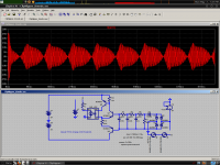
The current drive buffer is convenient in that it allows us to shape the filtering without anomalous effects from the LED impedance. We can also use small film caps, so the circuit is more reliable.
This is how it operates at 2x overload, adjusted for 13V threshold.
I was thinking, why not try to use a thermistor-based coupler? A heater+thermistor combination chip would be extremely configurable and useful, just by changing things like heatsink size, thermal resistance to PCB and such, and if the heater was close enough to the resistor it may be capable of reasonable response times. Dunno if such things exist though.
This new schematic allows for the use of much smaller film caps for the filtering, and is in many ways better. Thoughts:
I suppose you want immediate suppression of spontaneous transients, rather than a lingering drop in gain after a transient. The "lingering" is adjusted with R1. It could even be a knob.
R12 controls the threshold, it could be a knob too. I haven't looked into how I should reconcile the two redundant threshold controls, R12 and D5. Maybe delete D5? But then Q5's tempco would affect the threshold quite a bit.
The current drive buffer is convenient in that it allows us to shape the filtering without anomalous effects from the LED impedance. We can also use small film caps, so the circuit is more reliable.
This is how it operates at 2x overload, adjusted for 13V threshold.
I was thinking, why not try to use a thermistor-based coupler? A heater+thermistor combination chip would be extremely configurable and useful, just by changing things like heatsink size, thermal resistance to PCB and such, and if the heater was close enough to the resistor it may be capable of reasonable response times. Dunno if such things exist though.
Attachments
Last edited:
To get the loudest "transparent" limiting, the limiting threshold and gain reduction slope have to be dynamically adjusted depending on the amount of overdrive, how long the clipping events last and how frequent they are. The limiter has to learn about input signal. This imposes the need for a digital computer, or a thousand analog parts. Analog computers are a big no-no for mid/low-bandwidth mid/low-accuracy applications. That's the ideal application for a micro-controller. Each resistor, capacitor, transistor, diode is replaced by a few instructions, it's much cleaner in every aspect.
Last edited:
Sounds interesting!To get the loudest "transparent" limiting, the limiting threshold and gain reduction slope have to be dynamically adjusted depending on the amount of overdrive, how long the clipping events last and how frequent they are. The limiter has to learn about input signal. This imposes the need for a digital computer, or a thousand analog parts. Analog computers are a big no-no for mid/low-bandwidth mid/low-accuracy applications. That's the ideal application for a micro-controller. Each resistor, capacitor, transistor, diode is replaced by a few instructions, it's much cleaner in every aspect.
I'd love to see a design that can compete with the analog one in this thread
Oh, what have I done? T-amp loudness wars? lolz! This is so much like lawnmower races.
Digital could do the psycho-acoustic bass harmonic thing set to be engaged right on time when the amp is all run out of other resources to replay bass fundamental (aka fool the ear by playing the bass harmonics). That would sound as if louder cleaner bass. I don't quite know how to do that in analog.
Digital could do the psycho-acoustic bass harmonic thing set to be engaged right on time when the amp is all run out of other resources to replay bass fundamental (aka fool the ear by playing the bass harmonics). That would sound as if louder cleaner bass. I don't quite know how to do that in analog.
Here. I took me a while to track this one down...
HeadWize - Project: The Psychoacoustic Bass Enhancer by Jan Meier
HeadWize - Project: The Psychoacoustic Bass Enhancer by Jan Meier
Thanks for finding that!
Digital Ultrabass sidesteps the patent due to "a significant difference," but analogue does not and could not be sold for profit. The large size circuit, which doesn't come equipped with sensor and controller, is only one out of three analog circuits (limiter, harmonic bass, soft clipper) needed to supplant a small digital solution, with a huge analog solution. The size of the circuit seems to prove Eva's point. . . except that any size analog solution is still tunable with ordinary tools.
I'm actually still using the clipnipper limiter in post 1 because it works and sounds good. With that easy simple little limiter, the TA2020 does a great job on rockin the old RV on solar power. . . without clipping. The reason I didn't use Sure's much louder TA2024 is because the alternator voltage is 14.8v.
P.S.
Oh, terrible and good thought--the car radio also needs a clipnipper!
Last edited:
OVERLOADB, Pin 6, TA2020 inbuilt clipping indicator, Boominator?
From sx881663 posted here (link).
If it can operate an LED, it can also operate a 4n25 or LDR, right?
From sx881663 posted here (link).
If it can operate an LED, it can also operate a 4n25 or LDR, right?
Good idea Thank you very much.
Here's my ClipNipper limiter adjusted for TA2020, TA2024 with ~13vdc operating voltage. It is adjustable. I've got it running right now on the clipping prone TA2020. . . that's playing very loud without clipping. ClipNipper is a simple passive limiter that doesn't consume your battery power and it doesn't reduce useful output power at all, but what you get is a boost.
This schematic is currently up to date.
(log in to see schematic)
Notes ----------------------------------------------------------------------------------------------
Input:
As shown in the schematic above, the location of this fixed divider and its function is just like an ordinary 20k volume control turned almost all the way up. . . except for momentary LDR activations that prevent clipping.
Series resistance at input is within the range of 330 ohms to 1K whereby the larger value allows more volume fluctuation--set this to personal taste. I like 820R with the limiter version (schematic above) or 330R to 470R instead of 1k with the soft clip version (shown at post 12). Some optional gain management documentation is at post 17.
Substitutions:
3.1v Led: The 20ma+ 3.1v LED can be a white, Warm White, Green, Blue, Pink, or Purple LED.
2v Led: The 20ma+ 2v led in red, yellow, amber, orange can be used as four leds series plus two ordinary diodes series like (4*2v=8v)+(2*0.7v=1.4v)=9.4v total forward voltage drop, but I didn't test that--see settings/tuning below.
Schottky: You can use almost any Schottky or fast diode you happen to have instead of the Schottky diodes in my schematics.
Rectifier: The bridge rectifier doesn't have to be made of 1n4007. A miniature prefabricated bridge rectifier would work nicely too--the ~~ AC marks are for the speaker jack, but the +- marks run the ClipNipper limiter's LED's.
Settings/tuning:
It takes a bit of fine tuning, so have extra schottky (or fast silicon diodes) handy for that. If you need to trim a larger step, an amber or red LED is about 2v. More or less diode voltage drops in series to the LDR (led section) is how you set it. You'll have to try a variety of tracks before arriving at the setting that works best on average for your amplifier.
DIY CDS Optocoupler:
If there's not an LDR optocoupler handy, you can make one so easily. Just file the top of a white LED flat, then glue it to a CDS cell with clear glue, tape over the wires and paint that thing black. After it dries and after tape removal, you've got a DIY LDR optocoupler.
Battery management parts:
As a caveat of of its Zero standby drain design, ClipNipper will not reliably retard clipping for battery powered units with run down batteries unless the amp is run from a boost (or buck boost) type regulator. Eva's post #13 is a great idea for battery powered amp, but I couldn't figure out how to make that type of sensor work for bridge amp.
Larger scale amplifier applications:
Actually 3 LED's isn't enough for a larger scale amplifier, so for using ClipNipper to scrape the screech off of an LM3886 or even give the clean LM1875's a boost, you could start by simply adding more LED's and possibly a small change the drainer resistor value as needed for appropriate LED current. If one needs greater abruptness, one could use combination of zener and led instead of all led. Not all amplifiers/applications are equally dynamic. To track good dynamics without squashing, use more led, but to track lesser dynamics plus firmer control, employ some abrupt zener. Balance this out to track with your application and simply aim for pretty (pretty is better than clipping). The ClipNipper is interoperable with other limiters and soft clippers as well.
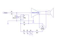
I tested the Clipnipper on a Tringlophone with the components kindly provided by Daniel.
Results
In mode "A" only (no comparison), the thing seems to work transparently, with no apparent distortion, pumping, or any other noticeable artefact.
However, in A/B mode (with/without), the sound is clearly duller with, in particular the attacks, that it seems to kill, or at least to blunt seriously (test was done with rock music).
After some trial and errors, I ended up with the version shown below: the capacitor across the coupler has been increased to 100µ, and a discharge resistor has been added to somewhat help the recovery and delay the onset of AGC action.
To compensate for the threshold, one of the LEDs has been shorted
On a purely technical level, I noticed that the I/V function of these couplers is non-linear; even the residual dark resistance is "S" shaped, which must introduce distortion. However, my tin ears failed to detect any distortion (not a surprise).
Attachments
Thanks for the update! Much appreciated!
I'm sorry that I forgot to mention that the original works with level tone only if you allow some of the amplifier's natural clipping pattern. However, the TV amp that I'm working on right now (for my mother) needs the AGC version you just posted. Thanks again!!
P.S.
The shorted D4. . . it might be interesting to replace that short with a small rectifier schottky(s) or a fast silicon diode(s) or 1n4007(s). Possibly that could add some more pretty/transparent flex usable for a touch more headroom. Any diodes with highly current reliant knee voltage can be used for trim--they don't actually have to be LED's.
P.P.S.
It could be interesting to put a 1k variable resistor in series with the light dependent resistor, so that the resistance can be fine tuned and "relaxed" as needed to preserve dynamics. LDR's vary a lot. Maybe the LDR that I sent was overly effective.
Last edited:
That's completely up to the user's taste, the power of the amplifier, how nasty it sounds when clipping, etc.P.S.
The shorted D4. . . it might be interesting to replace that short with a small rectifier schottky(s) or a fast silicon diode(s) or 1n4007(s). Possibly that could add some more pretty/transparent flex usable for a touch more headroom. Any diodes with highly current reliant knee voltage can be used for trim--they don't actually have to be LED's.
P.P.S.
It could be interesting to put a 1k variable resistor in series with the light dependent resistor, so that the resistance can be fine tuned and "relaxed" as needed to preserve dynamics. LDR's vary a lot. Maybe the LDR that I sent was overly effective.
Practically all parameters can be made tweakable, attack, decay, levels, etc.
It is impossible to provide a universal setting that would suit everyone, every type of music, equipment, etc.
The best option is to start with the basic parameters, and correct them to taste until the result is satisfactory
- Status
- This old topic is closed. If you want to reopen this topic, contact a moderator using the "Report Post" button.
- Home
- Amplifiers
- Class D
- LDR Limiter for TA2020, TA2024, spirited playback without clipping.