I believe it's an overload pin which activates when the amp clips. IIRC it's not suitable for driving an LED directly; I'd use something (4538 monostable multivibrator?) to stretch the pulse so an LED would stay on long enough to be visible. It's been on my roundtoit list to make up a little board for that purpose. You could use that buffered output to drive an integrator which would then drive the LDR. I'd be tempted to use a VCA for the gain element, like the SSM2164 (quad VCA). It looks like those are still available (AD says "last time buy"). Or the SSM2018T (single VCA); those are still listed as "production".
Last edited:
Ah, yes. The "clip something else" approach. I do favor that. The limiter in post one is already running just fine in several locations around the globe; however, we are in need of a high speed soft clipper, using something much faster than an LDR.I believe it's an overload pin which activates when the amp clips. IIRC it's not suitable for driving an LED directly; I'd use something (4538 monostable multivibrator?) to stretch the pulse so an LED would stay on long enough to be visible. It's been on my roundtoit list to make up a little board for that purpose. You could use that buffered output to drive an integrator which would then drive the LDR. I'd be tempted to use a VCA for the gain element, like the SSM2164 (quad VCA). It looks like those are still available (AD says "last time buy"). Or the SSM2018T (single VCA); those are still listed as "production".
For small scale amplifiers here are constraints for limiter:If this was set for "fast attack", "slow decay", it would automatically turn down the volume at the first sign of clipping. Maybe not what you're looking for, since that wouldn't be as loud overall compared to gently clipping those peaks.
Not catch the amplifier on fire. (observe current max)
Not make any sudden changes or noises. (must constrain extent)
Not decrease the bass output at all. (must avoid fast attack)
Just bear in mind that these circuits are interoperable with additional circuits and that any single effect must be constrained so that it is unnoticeable (transparent) in order to avoid sudden noise. But, you can indeed run multiple mild effects simultaneously if you wish to do so. For example, an extremely high speed soft clipper could be run on the same amp as the nice sounding limiter shown in post 1 and thereby provide a somewhat more complete feature set, since you would have both fast and slow features without removing output power. As a bonus, that combination will provide on-the fly "unclipper" audio restoration, but only when the amp is near max. That's right, it would soft clip a modern studio clipped source track, thus restoring it on-the-fly by removing the clipping prior to amplifying. That's a bit more fun to crank up.
P.S.
The limiter's constraints/parameters are much different between overpowered amplifiers versus underpowered amplifiers.
Last edited:
Another type of diode that works well for this application is the MR. The MR diode is a great help in mobile LED lighting refits because of its flexible switch on point. It actually switches on at 0.47v but will drop up to 0.75 with just a little bit of current (quite useful when in series). In this behavior, a big MR is much like a little schottky; however, the MR gives you a different voltage selection to choose from.
I tried substituting it instead of the schottky in post 1, and the MR worked. . . a little bit better. The transparency very similar; however, I thought there was subjectively a bit more bass. It was hard to detect any difference, therefore it worked well.
I tried substituting it instead of the schottky in post 1, and the MR worked. . . a little bit better. The transparency very similar; however, I thought there was subjectively a bit more bass. It was hard to detect any difference, therefore it worked well.
Try using a 2nd-order LP filter before the LED, or even third-order. This way, the high internal resistance of the 22uF lytic won't cause significant signal coupling to the LED, adding distortion to the signal, and filtering will be much more effective. If a transistor were used to drive the LED, smaller film caps could be used, though larger low-ESR lytics might work just as well considering there is no shortage of drive from the rectifier and amp output.
I don't have any subjective experience with any kind of sound limiter, so this is just based on my knowledge of electronics. I'm speaking from the standpoint of the coupler adding distortion as the rectified audio signal passes through it. I think you should experiment more with the LP filer, as I think it will have a larger impact on the sound than anything else.
Also, if the amp blows up and hits the rails, the LED or 390R resistor might be destroyed. A depletion FET could be placed in series with it for this purpose, to limit the LED current.
If there is DC across the input, the varying LDR resistor will add subsonic rumble when the circuit is activated. A capacitor in series with the LDR resistor may prevent this; moving the LDR after the amp's own DC coupling cap will only ensure a DC offset across the limiter because of the amp's input current. Maybe this rumble is a non-issue however.
Also, putting the negative end of the 22uF cap after the 390R resistor may increase filtering, as the impedance of the LED will raise the corner of the LP filter, nonlinearly with increasing LED current. Including the 390R resistor this way may help to stabilize the LP corner.
Thank you!
A good limiter, such as post 1, cannot "add" distortion since good signal does not pass the knee voltage of the detector, thus the circuit is off. . . until the amplifier starts to clip. Engagement of these devices should occur only "instead of clipping" and therefore it is a noise reduction device.
It is feedback, albeit tardy, and the lateness allows a slight clip and full bass impact shortly before clipping is temporarily disallowed.
There are adjustments/parameters:
There is extent (the input voltage divider), there is treble versus bass balance (that 22uF slows it down for clean treble) and there is engagement point (the sloppy knee voltages of LED and schottky help transparency).
The signaling is on purpose and highly desirable even though it is tardy. The 22uF cap swamps the timing error enough for clean voice and treble.
The extent (input voltage divider) was constrained until transparent; however, limiters that work better can be set to ride deeper and thus more effective without causing noise. There's always room for improvement, but making the limiter better also makes it progressively more difficult to improve.
Thank you for the input. I would greatly appreciate your help in protecting the LED's so as to be able to use ClipNipper with hundred watt amplifiers and not harm the LED's. For a hundred watt amplifier, we'd add a few more LED's for successful transparent engagement point, and then consider adding a zener to the chain.
Limiters make clean treble (because timer cap slows it down to avoid hashing the treble) but there will be "crunchy" bass when the amp is run well beyond max. That is correct for high efficiency limiter, since cutting that effect directly cuts the amplifier power (and we don't cut power output of 10 watt to 8R amplifiers).
Soft clippers run as fast as possible and make clean bass, but not clean treble, since they're not quite fast enough for treble. Can you make one go faster or fast enough?
I would love to have a working high speed soft clipper to clean the bass and use it in combination with my very nice limiter. I think that most of your post applies to soft clipper.
These two different circuits can be run together makes for clean audio band from bass to treble despite more decibels clean average output from the speaker. Compression occurs only instead of clipping, so compression does not occur when the amplifier is operated within its normal means. The trick is to keep the frequency response level, primarily have clean voice and treble (all that already done), and then try to provide loud clean bass.
I do have loud bass. But I don't have clean bass output well beyond the normal capacity of the amplifier. To do that needs a high speed soft clipper added.
A good limiter, such as post 1, cannot "add" distortion since good signal does not pass the knee voltage of the detector, thus the circuit is off. . . until the amplifier starts to clip. Engagement of these devices should occur only "instead of clipping" and therefore it is a noise reduction device.
It is feedback, albeit tardy, and the lateness allows a slight clip and full bass impact shortly before clipping is temporarily disallowed.
There are adjustments/parameters:
There is extent (the input voltage divider), there is treble versus bass balance (that 22uF slows it down for clean treble) and there is engagement point (the sloppy knee voltages of LED and schottky help transparency).
I would love to hear more about employing the depletion FET! That could really help when setting parameters for larger amplifiers that would be strong enough to break the LED's. The weak little T-amps aren't a problem, but I would like to apply this wonderful limiter to other amplifiers.Also, if the amp blows up and hits the rails, the LED or 390R resistor might be destroyed. A depletion FET could be placed in series with it for this purpose, to limit the LED current.
Post 1 lists the capacitor arrangement. Whatever noise that causes is entirely on purpose since it is better than clipping and acceptable since the device is off when clipping is absent.If there is DC across the input, the varying LDR resistor will add subsonic rumble when the circuit is activated. A capacitor in series with the LDR resistor may prevent this; moving the LDR after the amp's own DC coupling cap will only ensure a DC offset across the limiter because of the amp's input current. Maybe this rumble is a non-issue however.
The signaling is on purpose and highly desirable even though it is tardy. The 22uF cap swamps the timing error enough for clean voice and treble.
The extent (input voltage divider) was constrained until transparent; however, limiters that work better can be set to ride deeper and thus more effective without causing noise. There's always room for improvement, but making the limiter better also makes it progressively more difficult to improve.
Thank you for the input. I would greatly appreciate your help in protecting the LED's so as to be able to use ClipNipper with hundred watt amplifiers and not harm the LED's. For a hundred watt amplifier, we'd add a few more LED's for successful transparent engagement point, and then consider adding a zener to the chain.
Limiters make clean treble (because timer cap slows it down to avoid hashing the treble) but there will be "crunchy" bass when the amp is run well beyond max. That is correct for high efficiency limiter, since cutting that effect directly cuts the amplifier power (and we don't cut power output of 10 watt to 8R amplifiers).
Soft clippers run as fast as possible and make clean bass, but not clean treble, since they're not quite fast enough for treble. Can you make one go faster or fast enough?
I would love to have a working high speed soft clipper to clean the bass and use it in combination with my very nice limiter. I think that most of your post applies to soft clipper.
These two different circuits can be run together makes for clean audio band from bass to treble despite more decibels clean average output from the speaker. Compression occurs only instead of clipping, so compression does not occur when the amplifier is operated within its normal means. The trick is to keep the frequency response level, primarily have clean voice and treble (all that already done), and then try to provide loud clean bass.
I do have loud bass. But I don't have clean bass output well beyond the normal capacity of the amplifier. To do that needs a high speed soft clipper added.
Last edited:
Those LDR's aren't too slow, 250uS will still pass 1KHz. I think you should still listen to it with a high-order LP filter just to see. Take a few diodes out so it's operating constantly and tune it. The better LP filter allows you to raise the limit corner frequency without applying more limiting to higher frequencies. Thus you get less crunch, but better effective speed.
My experience is with bad amplifiers (I point no fingers here), bass quality may not be evidently important because you cannot imagine what the improvement would be. But with better amplifiers, where you get a spatial sense of the deep mid-bass room reverberations, it becomes evident that there is something unexpected to having quality in frequencies below 1KHz. My experience is that periodic transients, such as from unsnubbed rectifiers, seems to ruin this spatial imaging. I theorize that the diode transients cause shifting operating points in the amplifier, or ground noise. An input limiter could be treated the same way. I suspect that like the rectifier, if the limiter has it's own form of glitching, whether from not enough filtering or from diode glitches, then several overloads in a second may be enough to disrupt imaging and decrease sound quality; this can happen with normal music. So I think you should at least try it and see.
I will get a schematic ready. The problem I see with enhancement FET protection is that there might not be FETs that can pass 10mA at a high voltage for too long.
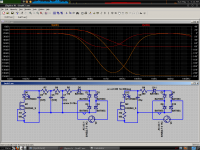
Here is an example. The DN2540 with 1W dissipation seems adequate, with a limit current of 10mA. The added 180R in series with the LED also stabilizes the LP corner. Read trace is LED voltage for the original version, orange is for the triple-LP version.
Attachments
For a fast treble limiter, maybe what you're looking for is just a diode clip circuit. A CFP can act as a very abrupt turn-on diode, which will cause less distortion before the clipping point. If the clipping is done before the amplifier itself clips, the gains may be significant even if it's not "soft".
You could also try an "ideal diode" such as the LTC4411.
You could also try an "ideal diode" such as the LTC4411.
For a fast treble limiter, maybe what you're looking for is just a diode clip circuit. A CFP can act as a very abrupt turn-on diode, which will cause less distortion before the clipping point. If the clipping is done before the amplifier itself clips, the gains may be significant even if it's not "soft". You could also try an "ideal diode" such as the LTC4411.
I had the same basic idea but didn't test it yet. A schottky based hard clipper with resistors added for a not so hard clip makes this soft clipper:
<rectifierschottky<led, resistor
>rectifierschottky>led, resistor
Nicely independent function there, good because music audio is asymmetric (except for radio broadcasts run through phase scramblers).
Even with the tiny voltage drop and near instant switch on of the 1N5819, it would still be quite hard to trim this for precision by adding more or less diodes. Well, not difficult, but the fine tuning would take some time. May also need elastics added in series to the above (elastics = schottky//resistor) to mitigate abruptness and led variances.
Well, that was the idea. Perhaps you can add some elegance?
Here is an example. The DN2540 with 1W dissipation seems adequate, with a limit current of 10mA. The added 180R in series with the LED also stabilizes the LP corner. Read trace is LED voltage for the original version, orange is for the triple-LP version.
Checking to see if I understood:
Replace the original 390R, 22u with:
120R, 22u; 120R 10u; 120R, 4.7u; pretty much as shown on your schematic?
This looks like you can use more capacitance (typically makes treble better, bass worse) without making the bass worse?
Could manufacture these near miss cap values:
10u//4.7u, 4.7u//2.2u, 2.2u//1u
14.7u, 6.9u, 3.2u
Would that be better?
I have a lot of electros, but not a lot of odd values.
P.S.
BAT85 rectifier? Wait per current before switch on function of a BAT signal schottky? I wasn't sure about the reverse voltage tolerance. The 1.4a high voltage silicon bridge rectifier (looks like a little round pill, costs 20 cents) has a "flexy" behavior similar to a schottky or at least close enough, so I used it.
I still seems like the best way to achieve low distortion and good clipping behavior is to just use a diode clipper and underrate the amp so that under normal listening conditions the diodes don't half-conduct.
What do you mean by "soft"? I thought you meant "not abrupt", in a timing sense, as an abrupt clip will be crunchy. It could also mean nothing to do with timing, just a non-abrupt transfer function. The problem with a non-abrupt transfer function is that it neither completely clips, nor is completely turned off. So my vote is for a abrupt transfer function, but a good LP filter, so harmonics are limited to the bass and mid-bass. Simple diode limiter for transients that occur too fast.
Problem with a diode limiter is that it's not very abrupt, so your amp will usually clip before the diode limiter turns on... And you have to overrate the amplifier output voltage by twice or more to keep the diodes completely off.
I just chose the rectifiers from my SPICE list, that one came from Cordell. As I recall, Schottkeys have lower breakover, but are less abrupt and have higher impedance at high currents. So I think silicon diodes are the best option for limiters. In an input limiter it is also important not to oversize diodes because the nonlinear capacitance can cause distortion depending on your source impedance. For the limiter rectifier though it shouldn't matter much.
The values of the caps aren't very important, just keep the general relationship. Actually I'm not sure if the value stepping matters here but I'm sure there is some economy to it. My reasoning is that C6 actually has 220R source resistance at LF, so it only needs to be half value. C5 has 330R, so 1/3 etc.
The values of the caps aren't very important, just keep the general relationship. Actually I'm not sure if the value stepping matters here but I'm sure there is some economy to it. My reasoning is that C6 actually has 220R source resistance at LF, so it only needs to be half value. C5 has 330R, so 1/3 etc.
Maybe we should consider the way we drive the LED. Depending on whether we use voltage or current drive, the LDR transfer curve will be some sort of log thing. Looking at this datasheet, it appears we want voltage drive, for logarithmic LED current, which will give logarithmic resistance, acting as a logarithmic volume limiter, which is what we need for audio.
http://www.silonex.com/datasheets/specs/images/pdf/104057.pdf
In this case a BJT buffer for the LED might be desirable so a series resistor is not needed to stabilize the LP corner. But then how to add current limit?
http://www.silonex.com/datasheets/specs/images/pdf/104057.pdf
In this case a BJT buffer for the LED might be desirable so a series resistor is not needed to stabilize the LP corner. But then how to add current limit?
The best approach is to use a micro-controller to evaluate input/output signals and set the amount of gain reduction dynamically. Electrically it's quite simple to implement: Just a PIC sensing input signal, output signal and rail voltage, and driving the LDR with PWM. Programming-wise finding good limiter control algorithms capable to adapt themselves to the signal being played is a little challenge.
")
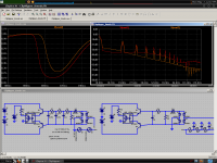
Another schematic. This illustrates the benefits of a high-order LP filter. High order harmonics are much lower. This is the result of an input voltage that is a combination of 500Hz and 490Hz, which produces a sine wave modulated at 10Hz, perfect for exploring limiter behavior.
Attachments
- Status
- This old topic is closed. If you want to reopen this topic, contact a moderator using the "Report Post" button.
- Home
- Amplifiers
- Class D
- LDR Limiter for TA2020, TA2024, spirited playback without clipping.