I'll agree that any solution using OPTOs is likly to have less distortion over a wider dynamic range then a FET solution. I couldn't find anything about the NE13600 you mentioned, but those nsl32 optos look very much like the ones I described from the surplus places. I have found them to be a good and inexpensive building block, BUT... I have found them to have VERY widely varying characteristics. Since I needed repeatability, I found it important to do some pre-testing and separate them into categories. Originally I was just looking at small differences in the LED diode forward voltage drop, but later found a much better method. Use a regulated 5V supply to drive the LED side through a 100K resistor, (about 32uA) and measure the resistance on the C-cell side. In doing so, I grouped mine into devices showing 2K-5K, 6K-12K, 30K-50K, and another group up over 250K, all with that same input! Anyway, sticking with one group (I stayed with the 2K-5K group) made it possible to get very consistent results from each circuit instance. My trim pot was still necessary for sure, but at least I was able to reliably duplicate the desired behavior.
I have just a simple question:
If we used two or three, mild, stacked/additive FET circuits, could we get the favorable range of the optos without the irritating component variance of the optos?
I asked because we might be in need of something like that. Well, I was just thinking that it would be really nice if we could make the fets work. Yeah, we know they don't, but the first person to do it for real should win at least a stick of gum, right? Who wants to win a 70 year old challenge and some gum?
Last edited:
yes i'm working on this again, the best soft clip/limiter so far i see is the incadesent bulb network. Bulbs are getting hard to find, and selections are narrow.
I still think a combination of both fast H11F1 opto and bulb will cure the issue.
We'll see, I'm doing a hybrid with TPA3118 PBTL output and need to implement a line level limiter.
I still think a combination of both fast H11F1 opto and bulb will cure the issue.
We'll see, I'm doing a hybrid with TPA3118 PBTL output and need to implement a line level limiter.

I have just a simple question:
If we used two or three, mild, stacked/additive FET circuits, could we get the favorable range of the optos without the irritating component variance of the optos?
I asked because we might be in need of something like that. Well, I was just thinking that it would be really nice if we could make the fets work. Yeah, we know they don't, but the first person to do it for real should win at least a stick of gum, right? Who wants to win a 70 year old challenge and some gum?
Gee... I just wonder if what you're proposing would multiply you're combined noise gains enough to create a new problem. I once felt the same way about Optos and tried some OTAs, and there again it was the noise that discouraged me. I'm not sure why opto circuits seem to turn out the quietest, but they always seem to for me.
You know, the more expensive optos (like the old VACTROLs if you can find genuine ones) seemed super consistent to me. Its the ones I was getting in the cheap "grab-bag" bulk packages that were the most inconsistent I'd seen. But after categorizing them I cut a few open, looked at the cadmium cells and lit the LEDs, and it became pretty obvious the reason for the inconsistency: they were made with several different groups of parts!!!! (LOL). I'm thinking that if I needed a lot of these, it would pay to start making my own. I'll bet with a bulk order of good cadmium cells and LEDs from the same company and lot, and a consistent assembly procedure, we could churn them out both cheaper and with excellent consistency!
Thanks for the information. That's approximately a "B"Gee... I just wonder if what you're proposing would multiply you're combined noise gains enough to create a new problem. I once felt the same way about Optos and tried some OTAs, and there again it was the noise that discouraged me. I'm not sure why opto circuits seem to turn out the quietest, but they always seem to for me.
You know, the more expensive optos (like the old VACTROLs if you can find genuine ones) seemed super consistent to me. Its the ones I was getting in the cheap "grab-bag" bulk packages that were the most inconsistent I'd seen. But after categorizing them I cut a few open, looked at the cadmium cells and lit the LEDs, and it became pretty obvious the reason for the inconsistency: they were made with several different groups of parts!!!! (LOL). I'm thinking that if I needed a lot of these, it would pay to start making my own. I'll bet with a bulk order of good cadmium cells and LEDs from the same company and lot, and a consistent assembly procedure, we could churn them out both cheaper and with excellent consistency!
Fine enough.
Did you really want to do just enough? I guess that is not what you should do.
Well, this thread was already over and done with before you joined. And, thank you for joining to contribute future. The thing is that if you're going to add something weird, then please don't fail it at. At this point please cancel any shyness. And please don't apologize, ever. Blaze forth!!!!
Thanks for the information. That's approximately a "B"
Fine enough.
Did you really want to do just enough? I guess that is not what you should do.
Well, this thread was already over and done with before you joined. And, thank you for joining to contribute future. The thing is that if you're going to add something weird, then please don't fail it at. At this point please cancel any shyness. And please don't apologize, ever. Blaze forth!!!!
Recall I started adding to this thread with cordial thanks, because I saw someone taking approaches with LDR limiters and compressors that reflected some of my own experiments. Sorry if you feel I hijacked your thread. But in a public forum I usually learn some things, reject others, and post when I believe others might find some things in my posts useful too. If that's not you, go ahead and insult away. What exactly in my proposal to make my own LDRs is a "B"? Or "Weird" for that matter? Is "B" supposed to be a grade? If so, that's a little bit funny. If I'm taking this the wrong way, please explain. But if anyone seems to be starting to "blaze" here, its not me. And as with political discussions, I stop response to individuals completely once the tone changes to insult.
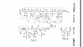
here is another from Eric Prichard, just found by accident.
Body of patent (expired) has description of fig 7.
https://patentimages.storage.googleapis.com/pdfs/US4809336.pdf
Body of patent (expired) has description of fig 7.
https://patentimages.storage.googleapis.com/pdfs/US4809336.pdf
Attachments
Last edited:
This thread was over before you joined, so I'm just really glad that you arrived and made it more interesting.Sorry if you feel I hijacked your thread.
P. S.
Although our applications are considerably different (music replay vs guitar performance), I do appreciate your input on alternative uses of the same parts. Thanks!
ClipNipper is a simple passive on-demand (doesn't activate until needed) compressor (booster like the Volumax) that doesn't consume your battery power and it doesn't reduce useful output power, but what you get is a headroom boost. This device mitigates/reduces clipping but it will not block everything and thus it doesn't reduce your bass. It will mimic the headroom advantage of a good tube amp.
This schematic is currently up to date.
(log in to see schematic)
Notes ----------------------------------------------------------------------------------------------
Input:
As shown in the schematic above, the location of this fixed divider and its function is just like an ordinary 20k volume control turned almost all the way up. . . except for momentary LDR activations that constrain clipping.
Series resistance at input is within the range of 330 ohms to 1K whereby the larger value allows more volume fluctuation--set this to personal taste. I like 820R. Some optional gain management documentation is at post 17.
Substitutions:
3.1v Led: The 20ma+ 3.1v LED can be a white, Warm White, Green, Blue, Pink, or Purple LED.
2v Led: The 20ma+ 2v led in red, yellow, amber, orange can be used as four leds series plus two ordinary diodes series like (4*2v=8v)+(2*0.7v=1.4v)=9.4v total forward voltage drop, but I didn't test that--see settings/tuning below.
Schottky: You can use almost any Schottky or fast diode you happen to have instead of the Schottky diodes in my schematics.
Rectifier: The bridge rectifier doesn't have to be made of 1n4007. A miniature prefabricated bridge rectifier would work nicely too--the ~~ AC marks are for the speaker jack, but the +- marks run the ClipNipper's LED's.
Settings/tuning:
It takes a bit of fine tuning, so have extra schottky (or fast silicon diodes) handy for that. If you need to trim a larger step, an amber or red LED is about 2v. More or less diode voltage drops in series to the LDR (led section) is how you set it. You'll have to try a variety of tracks before arriving at the setting that works best on average for your amplifier.
Stereo:
CDS LDR's never match, but that isn't difficult. To get the LDR's to work most easily, build atop a 20k volume pot with the LDRs from wiper to ground and from 820R to 1K series resistors at input (or just turn the pot dial slightly off of max if you intend to replace the pot with equivalent resistors later). With the LDR's off then parallel the weakest with a resistor to make the channels match. Parallel with the LDR's is also a decent spot for a picofareds cap if the circuit is used in radio production environment. And with the LDR's On adjust the detector's bias resistor (and/or add series resistance to the strongest LDR) to make the channels match. Lastly, you can substitute the 20k pot for equivalent resistors, if desired, or you can keep the pot as a volume control that refuses to clip (if you add resistors to the input of the pot). For stereo, the matching up seems like a slight bother, but it is quite fast to do since the pot has already conquered most of the variance.
LDR Optocoupler:
It is important to find an LDR that can pull down to 1K, but if this can't be found, then it is possible to put several (of the resistor sections) in parallel. The problem with an LDR that only pulls down to 10K is that you'd have to set it to engage much too early, and we wouldn't want to do that.
DIY CDS Optocoupler:
If there's not an LDR optocoupler handy, you can make one so easily. Just file the top of a white LED flat, then glue it to a CDS cell with clear glue, tape over the wires and paint that thing black. After it dries and after tape removal, you've got a DIY LDR optocoupler.
Battery management parts:
As a caveat of of its Zero standby drain design, ClipNipper will not reliably retard clipping for battery powered units with run down batteries unless the amp is run from a boost (or buck boost) type regulator. Eva's post #13 is a great idea for battery powered amp, but I couldn't figure out how to make that type of sensor work for bridge amp.
Larger scale amplifier applications:
Actually 3 LED's isn't enough for a larger scale amplifier, so for using ClipNipper to scrape the screech off of an LM3886 or even give the clean LM1875's a boost, you could start by simply adding more LED's and possibly a small change the drainer resistor value as needed for appropriate LED current. ClipNipper can be powered by a preamplifier, which may be both more convenient and more durable than adding it directly to a big power amp (see the datasheet for led max current figure). If one needs greater abruptness, one could use combination of zener and led instead of all led. Not all amplifiers/applications are equally dynamic. To track good dynamics without squashing, use more led, but to track lesser dynamics plus firmer control, employ some abrupt zener. Balance this out to track with your application and simply aim for pretty (pretty is better than clipping).
ClipNipper does not contain peak protection but can reduce the duration of overload conditions by turning down the volume. The ClipNipper is interoperable with other limiters and soft clippers as well (see Cordell's KleverKlipper)--simply adjust the ClipNipper compressor to engage first. And, that can be useful with the chip based amplifiers, to approximately hold the frequency response level instead of listening to a chip amplifier's inbuilt limiter.
Update:
At post 58, Elvee has modified the ClipNipper to support Class A Tringlophone.
Update:
Good place to buy LDR's: http://www.buildanamp.com/2-Light-Dependent-Resistors-LDRs_c2.htm
")
How to set threshold voltage from where limiter start action to limit audio gain.?
The circuit as illustrated, with the series LED's, and then to support a bigger amp, put a zener series to the LED's.How to set threshold voltage from where limiter start action to limit audio gain.?
You an also consider running those diodes off a variable voltage divider (potentiometer).
Also, follow this link: Audio Amp Power Limiter
Fairchild's H11F3M Photo FET Optocoupler could really help this type of project. They're more consistent than LDR/CDS tech.
Datasheet: http://www.mouser.com/ds/2/149/h11f1m-185284.pdf
Unless you want your input load to suddenly switch to 470R, you'd probably want a series resistor for the fet, and a parallel 22u cap for the LED. It is very useful to put a visible led series to the inbuilt led so that you can see what is happening, and when--make sure it stays dark until the amp starts to clip.
- Status
- This old topic is closed. If you want to reopen this topic, contact a moderator using the "Report Post" button.
- Home
- Amplifiers
- Class D
- LDR Limiter for TA2020, TA2024, spirited playback without clipping.