Send me an email to oszappa@yahoo.com or oszappa@gmail.com, I´ll send it attached.
I've just send an email to you, thanks for your offer.
This is how far I managed to get till now:
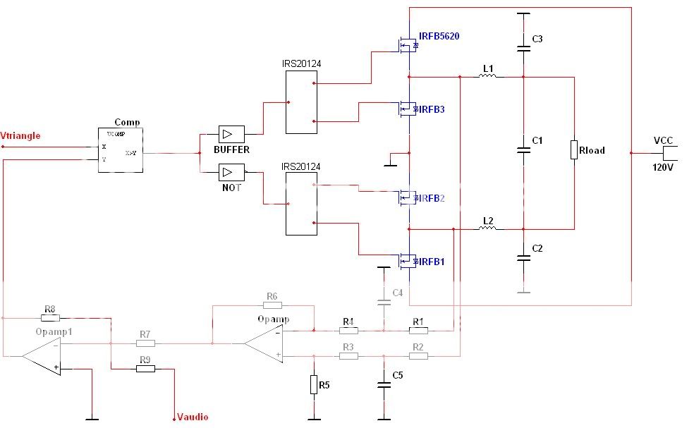
The circuit you posted looks well, but the components arround the filter, sincerelly, don´t. In the scheme I was adopted in my project, the operational itself was the active filter, more than a filter, an integrator, placing a cap between in- to out, a R in that input, and similar R to + input with a C to ground, like figure 5 of the work from Marshall I suggested, but the other input op input (+) wired by a similar network from the other pole of the load, and the cap to gnd, obviously. So you get ridof the phase rotation inside the opamp prior to the integrator.
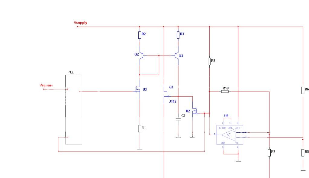
Which kind of triangle generator will you use?
Which kind of triangle generator will you use?
Last edited:
The circuit you posted looks well, but the components arround the filter, sincerelly, don´t. In the scheme I was adopted in my project, the operational itself was the active filter, more than a filter, an integrator, placing a cap between in- to out, a R in that input, and similar R to + input with a C to ground, like figure 5 of the work from Marshall I suggested, but the other input op input (+) wired by a similar network from the other pole of the load, and the cap to gnd, obviously. So you get ridof the phase rotation inside the opamp prior to the integrator.
Which kind of triangle generator will you use?
A self developed one, I've posted it in this message as you can see.
The line of J112 and the line of R7 are connected.
Last edited:
The circuit you posted looks well, but the components arround the filter, sincerelly, don´t. In the scheme I was adopted in my project, the operational itself was the active filter, more than a filter, an integrator, placing a cap between in- to out, a R in that input, and similar R to + input with a C to ground, like figure 5 of the work from Marshall I suggested, but the other input op input (+) wired by a similar network from the other pole of the load, and the cap to gnd, obviously. So you get ridof the phase rotation inside the opamp prior to the integrator.
Which kind of triangle generator will you use?
About active filtering, this amplifier = 1500W, I can't think of a way to filter 120Vdc/12.5A active. So I should probably filter active in my feedback circuitry? Would you mind giving a clear description about the error in my filter vs. a better option?
About active filtering, this amplifier = 1500W, I can't think of a way to filter 120Vdc/12.5A active. So I should probably filter active in my feedback circuitry? Would you mind giving a clear description about the error in my filter vs. a better option?
120 VDC is not a trouble, with high ohmic value and a small cap, an integrator can be easily done, More, you can put several small value resistors in series to share voltage and reduce self capacitance. I done such a thing in my own project.
I can send you a copy of mine, but do you have a program called OrCAD for DOS? I have libraries and circuits to this old good stuff.
I don't, can you send it to me / post it here as an image? (.jpg or something that looks alike)
I don't, can you send it to me / post it here as an image? (.jpg or something that looks alike)
I´ll try to get a file translator, and I send it when I can.
Best Regards.
I´ll try to get a file translator, and I send it when I can.
Best Regards.
Printscreen --> Paint (ctrl + V)
Printscreen --> Paint (ctrl + V)
In this ******* PC this doesn´t work.
Hey, I'm encountering a new design problem.
How do I calculate the pull-up resistor connected to the overcurrent sense of the IRS20124?
Any value of about 10K to 100K will work. This is an open drain output, so the value depend on where this signal will drive.
Hey, I'm encountering a new design problem.
How do I calculate the pull-up resistor connected to the overcurrent sense of the IRS20124?
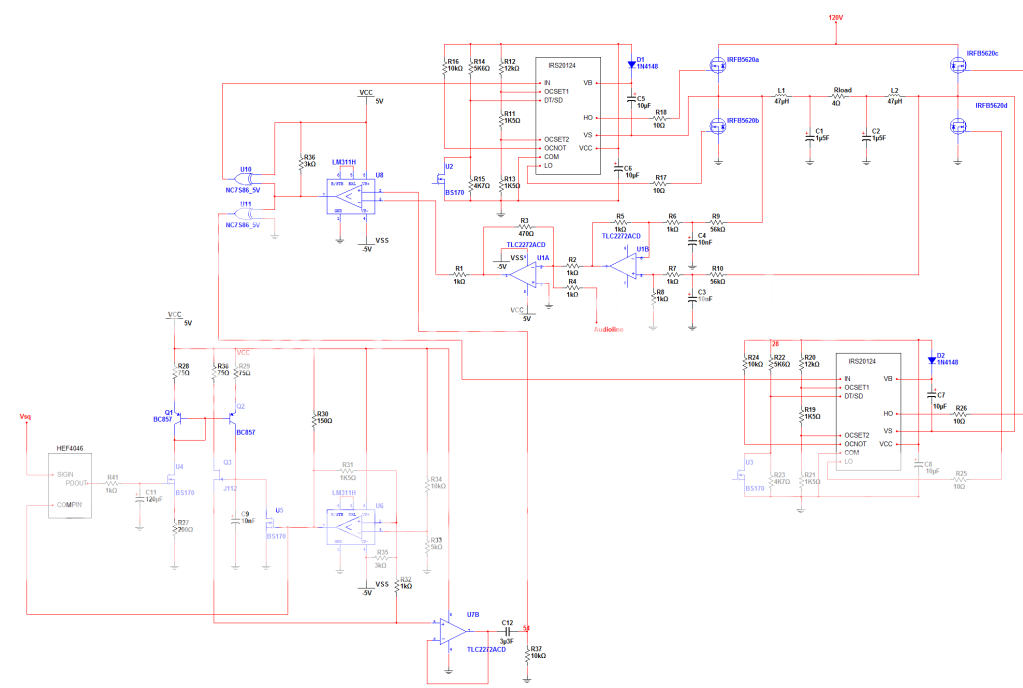
another schedule, this time it's of the entire system.
An externally hosted image should be here but it was not working when we last tested it.
Got a few problems:
the Values of R16,R24,C5,C6,C7,C8.
And is this feedback loop strong enough if I have an audio signal of 1.23 Vrms?
Edit:
oh you answered the question about R16,R24.
I found a minor fault in my schedule, please remind that the ground on the negative supply of U7B should be -5V
Last edited:
- Status
- This old topic is closed. If you want to reopen this topic, contact a moderator using the "Report Post" button.
- Home
- Amplifiers
- Class D
- Incorrect fetdriving?