Hi Savu
hello just some tips i need to know before i start this project
1 will single PCB be good enough for this amp as i have little experience in designing ds pcb
2 can IRFP 250 N be used for experimental purpose once amp working irfb4227 will
be used
3 ultra fast ic LT1711 ANY substitutes this ic hard to get in my city
savu with little help from you i think i can suceed in my project
thanking you
sameer x1
Let me answer instead if Savu
1. If you have little exp, then a single sided PCB will suffer noise problmes etc. Layout is one the most important parts in Class-D
2. If you want to experiment with cheaper FETs, use IRF640N, since IRFP250N will have very high switching losses. For good performance you will need expensive FETs.
3. Search for outher ultra fast comparators with simmetrical output like: TL3016, LT1016, TL712
PCB LAYOUT
Hi Lorylaci
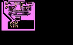
hello just need to know if this layout can work for the schematic savu posted its rough layout ground trace is around most components what more tips
must i do to make pcb suitable for this amp i am new to d class pcb designing
any tips are most welcome always a first time thats how i will learn
thanking you
sameer x1
Hi Lorylaci
hello just need to know if this layout can work for the schematic savu posted its rough layout ground trace is around most components what more tips
must i do to make pcb suitable for this amp i am new to d class pcb designing
any tips are most welcome always a first time thats how i will learn
thanking you
sameer x1
Attachments
Hi Lorylaci
hello just need to know if this layout can work for the schematic savu posted its rough layout ground trace is around most components what more tips
must i do to make pcb suitable for this amp i am new to d class pcb designing
any tips are most welcome always a first time thats how i will learn
thanking you
sameer x1
There seems to be errors with connections. Also you should check all the current loops, they seem to be going round noise sensitive tracks.
Sameer, for first try, rail voltage should 50-0, gate resistor also need to increase, u need to pass for the pcb first, hope lorylaci can help u with pcb error.
Pafi... where r u? hehehe Luka? Make IR2110 FullBridge alive for our Diyers
As I sead before there are problems with IR2110. On a Hungarian forum, a forum member Gee Lee experimented with it (see here: Google Fordító)
And he could only make it with compromises. The minimum pulse width of IR2110 makes it impossible to use fast comparators, and to use high modulation limit (modulation limit over 70% causes high distortion).
Sorry to say that, but I hate if somebody wants everything complete. A page ago I posted an idea, I can even post its layout, if you want.
FullBridge +/- 65? lol... its for PA use hehe Yah i agree with you they need to start at first build, so maybe anyone wanna start making pcb for full bridge? I`ll not making it with IR2110 with fullbridge, if i want i just make 2 pcb and bridge it.
p/s - your protection on schematic work?
Yah i agree with you they need to start at first build, so maybe anyone wanna start making pcb for full bridge? I`ll not making it with IR2110 with fullbridge, if i want i just make 2 pcb and bridge it.p/s - your protection on schematic work?
FullBridge +/- 65? lol... its for PA use hehe
p/s - your protection on schematic work?
In this schematic Gee Lee simpli bridged two moduls. This has a con that there is soem interferrence. If you make it on two separate PCB the interferrence is much bigger.
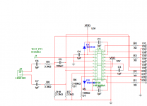
Are you interested in the HIP4080A plan? Its a full bridge (single supply max 72V), and I have a layout for that.
Hi lorylaci,
Its looks like great project, hmm i need to find hip ics first, i dont have it yet. and what about the layout? im not good in making pcb design, very bad ... damn.
Attached is the layout, in sprint layout format. I haven't tested it yet, but it is an amp based on UcD, and has a good predicted performance. HIP4080A has an ability to set dead-time, and has a very fast input comparator, and fast propagation delay. So modulation limit can be very high (which enables you to use the supply to maximum).
Attachments
cool, very simple and few components, where is the parts details?
In previous page, you will find the schematic, I posted.
Most components are 1206 SMD ones (can be hand soldered). Planned inductors are Coilcraft special ones. Here you find info about them: Coilcraft VER2923 High Current Power Inductors
got it, but schema have comparator and layout dont include it? it works?
Please, use a little more specific english, because I cannot understand you.
HIP4080A is an integrated full-bridge driver, with integarated ultrafast comparator. So no external comparator is needed.
I haven't tested it yet, the PCB is ready, but I am working on my Master's Thesis Work, so maybe on Easter holidays.
im refer to this schema http://www.diyaudio.com/forums/atta...upply-bridge-ucd-referencing-signals-ucd1.pdf
which include comparator at the input stage and having fb out from it, but on layout u give me feedback is directly come from HIP and not using comparator, or maybe i`m refer to wrong schema.
which include comparator at the input stage and having fb out from it, but on layout u give me feedback is directly come from HIP and not using comparator, or maybe i`m refer to wrong schema.
im refer to this schema http://www.diyaudio.com/forums/atta...upply-bridge-ucd-referencing-signals-ucd1.pdf
which include comparator at the input stage and having fb out from it, but on layout u give me feedback is directly come from HIP and not using comparator, or maybe i`m refer to wrong schema.
The one you linked, is not my schematic. Mine is here: http://www.diyaudio.com/forums/class-d/207145-ucd-project-subwoofer-class-d-amp-full-h-bridge-single-supply-50-v-2.html#post2933972
Its gone...
Oops! Google Chrome could not connect to kepfeltoltes.hu
Then here you go, see attached.
Attachments
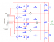
gate resistor 3 ohm? I would try with cheap mosfet like irf540 without N, what about gate resistor? 27 ohm?
You must get at least an IRF540N, forget Class-D without good mosfets. Even for testing, an IRF540N will be bad. IRF540Z is cheap, and usually easy to get. I planned using FDP3652.
3 or 27 ohm? You must change the dead-time, not the gate driving resistor, to avoid cross-conduction (according to your chosen FETs). You can only use higher gate resistors for very small gate charge FETs like IRF6645.
- Status
- This old topic is closed. If you want to reopen this topic, contact a moderator using the "Report Post" button.
- Home
- Amplifiers
- Class D
- UcD project, Subwoofer class d amp, full h-bridge, single supply +50 V