Go for LM361 which has same specs 20nS delay and complementary outputs but also works on +/-15V like an opamp frontend and +5V for logic interface
Thanks you too workhorse, its sightly more expensive but worthwhile supporting the +/- 15V voltage selection. looking at the datasheet and the nice thing is my local supplier has stock of these
Some progress:
Moving along swiftly... and reading other material on the forum going back two years ago (and lots of patience) ... vie made it until this point with no smoke or component death...
The following is the from the MGD IR2110 (Notice the overshot on the yellow trace its a bad probe , i swopped it around and it didn't show up need get a better probe)
No dead-time has been employed (for now) .. vie grounded PIN VS to (-V 21) to give symmetrical output from the driver just to debug the switching nodes and observe switching behavior.
IR2011 Outputs are switching cleanly between 800mv to 13.8V with no noise artifacts ( taking into consideration its an old bread board)
Using a for 15V regulator i wonder if should step it up to something like an 18V regulator.. will it give better switching results as the gate is charged more effectively.
Moving along swiftly... and reading other material on the forum going back two years ago (and lots of patience) ... vie made it until this point with no smoke or component death...
The following is the from the MGD IR2110 (Notice the overshot on the yellow trace its a bad probe
, i swopped it around and it didn't show up need get a better probe) No dead-time has been employed (for now) .. vie grounded PIN VS to (-V 21) to give symmetrical output from the driver just to debug the switching nodes and observe switching behavior.
IR2011 Outputs are switching cleanly between 800mv to 13.8V with no noise artifacts ( taking into consideration its an old bread board
) Using a for 15V regulator i wonder if should step it up to something like an 18V regulator.. will it give better switching results as the gate is charged more effectively.
An externally hosted image should be here but it was not working when we last tested it.
My interpretation would be different.The following is the from the MGD IR2110 (Notice the overshot on the yellow trace its a bad probe
The signal without ringing is looking by far to slow to be the correct output of an unloaded IR2110. With the shown time scale the sloping times of the IR should be a perfect real vertical step, invisible rise time. In your screen shot we can guess 100-200ns, but the IR typically slopes unloaded within 20ns. The round edges of the trace make me guess that the concerned probe is pretty slow, or not adjusted correctly.
The trace with ringing could be correct. It is rising fast, fitting to IR. It shows ringing, fitting to breadboards.
Another option could be that both wave forms are not fully correct, if both probes are not perfectly adjusted. Note, fast probes sometimes have two adjustments.
800mV is also strange. It should be close to zero.IR2011 Outputs are switching cleanly between 800mv to 13.8V with no noise artifacts ( taking into consideration its an old bread board
Offset? Do you get really zero, when shorting the probe?
No, the higher voltage will not bring much advantage. Note when you put a higher driving voltage you may reach the ON-plateauvoltage slightly faster, but in turn it will need longer to turn OFF. You can slightly influence the effective dead time by this, but won't getter a better quality of the gate drive signals. The gate drive signal quality will depend more on the PCB layout and MosFet properties.Using a for 15V regulator i wonder if should step it up to something like an 18V regulator.. will it give better switching results as the gate is charged more effectively.
Last but not least, unnecessary high drive voltages will result in unnecessary gate drive losses.
P.S.
Basically your signals do look reasonable.
My interpretation would be different.
The signal without ringing is looking by far to slow to be the correct output of an unloaded IR2110. With the shown time scale the sloping times of the IR should be a perfect real vertical step, invisible rise time. In your screen shot we can guess 100-200ns, but the IR typically slopes unloaded within 20ns. The round edges of the trace make me guess that the concerned probe is pretty slow, or not adjusted correctly.
The trace with ringing could be correct. It is rising fast, fitting to IR. It shows ringing, fitting to breadboards.
Another option could be that both wave forms are not fully correct, if both probes are not perfectly adjusted. Note, fast probes sometimes have two adjustments.
800mV is also strange. It should be close to zero.
Offset? Do you get really zero, when shorting the probe?
No, the higher voltage will not bring much advantage. Note when you put a higher driving voltage you may reach the ON-plateauvoltage slightly faster, but in turn it will need longer to turn OFF. You can slightly influence the effective dead time by this, but won't getter a better quality of the gate drive signals. The gate drive signal quality will depend more on the PCB layout and MosFet properties.
Last but not least, unnecessary high drive voltages will result in unnecessary gate drive losses.
P.S.
Basically your signals do look reasonable.
Probe number 2 (yellow) is definitely faulty it cannot seem to read fast signals, the internal from the scope calibration (1Khz @ 5V) the yellow probe reads fine however, after probing faster switching nodes from the modulator (250Khz) it shows ringing that's not present i have proved it by using the probe 1 (red) and being able to measure the faster 250khz signal node.. im only using dual trance mode to view symmetrical output from the driver and at the moment as im tying dead-time as promised previously i really need to get a reliable probe else i will be chasing ghosts as Eva put it..
I'm sure the doesn't exists from the breadboard the (red) probe reads a clean switching events.. see below
An externally hosted image should be here but it was not working when we last tested it.
The signals from the IR2110 are starting to look great (and professional
) at the moment vie re-calibrated my scope and probes, the results show a clean switch betweenLOW0.0mV HIGH 13.40V
As for the gate drive voltage increase idea, i will stay with the existing 13+ volts feeding the mosfets, I'm just about introduce the dead-time, its set to 130ns (I guess this is to high) but, for now testing its okay i will reduce dead-time to 50ns or so later as well as switching frequency at a later stage.I don't feel the need to switch the modulator this fast ie: (255Khz) reducing this as well to 150Khz maybe later..
I'm starting to get nervous, as its almost time to introduce the mosfets vie got a pair of IRF640 laying on my desk (yes for now i will use them and upgrade to something better at a later stage)
Last edited:
Just looked at some entries on the forum regarding dead-time was really dead simple to follow using RCD approach after the XOR gates set to 140ns
This is the results after introducing dead-time (Note: ignore the yellow probe overshot i will replace this probe) (I know its awfully high)
This is the results after introducing dead-time (Note: ignore the yellow probe overshot i will replace this probe) (I know its awfully high)
An externally hosted image should be here but it was not working when we last tested it.
Yup, here the red one is looking blameless and sloping speed would also fit to the IR driver.
Definitely nice!
I feel sleepy
excitement tells me to wire up the mosfets now but common sense tells me i cant concentrate now, i feel vie achieved enough today will look at the mosfets and LP filter over the next few days i know the real fun and headaches only starts when the filter and signal drive is applied to the circuit... Thanks for the assistance thus far Chocolate !
It's a question of experience, familiarity and mindset. When asked for a solution to a problem, one tends to use the tools one is most familiar with, regardless of objective fit.
Case in point, your own post!
PIC 1F628A Protection
That's putting the cart in front of the horse; instead of just stating "firmware", or "uC" you impose a specific architecture and a specific model right from the beginning. Presumably because you happen to be familiar with the PIC1F628A. By analogy, analog
Cheers,
E
Choose a PIC with ADC and you will be able to avoid some analog protection circuitry and make the protections much more flexible. It will be a good chance to start learning low level DSP programming (doing simple IIR and FIR filters in assembler or C, ie: DC protection requires a LPF, why using a big cap when you can do it in software? FilterShop is a very valuable tool). For example you can use 16F684 or 16F690. They are similar to 16F628, which is similar to 16F84. If you want something more advanced, go for the new 16F1823/4/5/9, with 32Mhz internal clocks and extended instruction set, which are likely to replace all the other ones I mentioned in the future.
btw: I'm working in hybrid digital/analog PFC now, with analog current loop and a novel digital voltage loop. Next step will be fully-digital single-micro PFC, specially designed for single stage audio SMPS (excellent transient response without tons of bulk capacitance or very poor P.F.). In a world of finite resources, part counts and the cost of each part must be kept low, while getting as much as possible out of each part and the the topology. This requires developing complex control algorithms. The ideal electronics designer of 21st century must be a skilled programmer too. Too much specialization makes you weak and easy to exploit by unfair employers (people willing to eran 10 times more money than you with 10 times less skills, no mercy on them! I'm with 15M people)
Last edited:
Choose a PIC with ADC and you will be able to avoid some analog protection circuitry and make the protections much more flexible. It will be a good chance to start learning low level DSP programming (doing simple IIR and FIR filters in assembler or C, ie: DC protection requires a LPF, why using a big cap when you can do it in software? FilterShop is a very valuable tool). For example you can use 16F684 or 16F690. They are similar to 16F628, which is similar to 16F84. If you want something more advanced, go for the new 16F1823/4/5/9, with 32Mhz internal clocks and extended instruction set, which are likely to replace all the other ones I mentioned in the future.
btw: I'm working in hybrid digital/analog PFC now, with analog current loop and a novel digital voltage loop. Next step will be fully-digital single-micro PFC, specially designed for single stage audio SMPS (excellent transient response without tons of bulk capacitance or very poor P.F.). In a world of finite resources, part counts and the cost of each part must be kept low, while getting as much as possible out of each part and the the topology. This requires developing complex control algorithms. The ideal electronics designer of 21st century must be a skilled programmer too. Too much specialization makes you weak and easy to exploit by unfair employers (people willing to eran 10 times more money than you with 10 times less skills, no mercy on them! I'm with 15M people)
I was thinking along same lines regarding PIC based controlled protection schemes, its really fun and interesting employing software protection schemes (but hard asat the same time its rather a steep learning curve especially in the DSP arena where few dare go
) The idea of the IIR and FIR filter with ADC is great however, can one do low pass filter DSP using an 8-bit uC using the ones you mentioned above ??
Ive looked at the filter coefficients and ALL of them use double precision, 8-Bit MCU memory cant store word lengths this wide can it?? confused face
FilterShop looks great really amazing tool looking at that now...
Last edited:
There are many shortcuts for making simple digital filters with 8 bit micros, using fixed point and replacing the multiplications by shift and add/sub operations. This is a simple 6dB/oct IIR LPF. It's called a "recursive filter" when done that way:
LPF_ACCU-=LPF_ACCU>>S
LPF_ACCU+=NEW_VALUE
LPF_OUTPUT=LPF_ACCU>>S
And this little basic program tells you filter cutoff depending on S and FS (sampling freq.)
10 FS=1000:S=8
20 SC=(-1/LOG(1-1/2^S)):TC=SC/FS:FC=1/(2*3.1415*TC)
30 PRINT "Fs=";FS;" S=";S;" Sc=";SC;" Tc=";TC;" FC=";FC
Another application of this code is to get extra precision out of the ADC by oversampling and then LPF. 2^n oversampling adds n/2 bits of precision at the output of the LPF.
Keep this info for later. You still have a lot of work to do to get class D working.
Last edited:
btw: If it was not already obvious for you, 2/3/4 consecutive bytes are routinely used to work with 16/24/32 bit numbers in 8 bit micros. This also requires 2/3/4 add/sub/shift operations, and managing carry bits properly. PIC16F84, 16F628, 16F684, 16F690 and similar ones (very simple families) neither have an "add with carry" nor a "sub with carry" instruction, but there is a fix (with a skpc/skpnc and a incfsz), or you can just use C and leave that work for the compiler, but it won't do wonders regarding efficiency, compilers just make functional code.
Last edited:
[...] The ideal electronics designer of 21st century must be a skilled programmer too. Too much specialization makes you weak and easy to exploit by unfair employers (people willing to eran 10 times more money than you with 10 times less skills, no mercy on them! I'm with 15M people)
 Words of wisdom here!
Fond memories of writing a double-precision math package for a Z80 bubbling up...Reactance said:Ive looked at the filter coefficients and ALL of them use double precision, 8-Bit MCU memory cant store word lengths this wide can it??
There are many shortcuts for making simple digital filters with 8 bit micros, using fixed point and replacing the multiplications by shift and add/sub operations. This is a simple 6dB/oct IIR LPF. It's called a "recursive filter" when done that way:
LPF_ACCU-=LPF_ACCU>>S
LPF_ACCU+=NEW_VALUE
LPF_OUTPUT=LPF_ACCU>>S
And this little basic program tells you filter cutoff depending on S and FS (sampling freq.)
10 FS=1000:S=8
20 SC=(-1/LOG(1-1/2^S)):TC=SC/FS:FC=1/(2*3.1415*TC)
30 PRINT "Fs=";FS;" S=";S;" Sc=";SC;" Tc=";TC;" FC=";FC
Another application of this code is to get extra precision out of the ADC by oversampling and then LPF. 2^n oversampling adds n/2 bits of precision at the output of the LPF.
Keep this info for later. You still have a lot of work to do to get class D working.
Hey Eva.
Thanks for the brilliant explanation with prove (why didn't you just write it in plain C
) I will archive this as DSP PIC knowledge base info going forward, when my amp is working i will go forth with PIC based protection schemes... now as you said i have lots of other research to complete with this project.
I don't think im going to be deeply involved researching the "ultimate class d-modulator" like vie seen everyone else has done here.. the clock based one works for me and all i wanted is a killer sub-woofer amp with a professional feel to it with a micro-controller based protection scheme..
I'm investing in a better programmer like the PICKIT-3 is it better than the PICKIT-2 whats your view on this??? vie heard many stories and im getting the vibe that past experiences using the PICKIT-2 are better...
Last edited:
btw: If it was not already obvious for you, 2/3/4 consecutive bytes are routinely used to work with 16/24/32 bit numbers in 8 bit micros. This also requires 2/3/4 add/sub/shift operations, and managing carry bits properly. PIC16F84, 16F628, 16F684, 16F690 and similar ones (very simple families) neither have an "add with carry" nor a "sub with carry" instruction, but there is a fix (with a skpc/skpnc and a incfsz), or you can just use C and leave that work for the compiler, but it won't do wonders regarding efficiency, compilers just make functional code.
Okay i can tell you write a *ALOT* of all your code in pure ASM
Im using *mikroc-pro* its rather easier and faster to get a prototype working..
mikroElektronika - mikroC PRO for PIC - C compiler for Microchip PIC microcontroller development
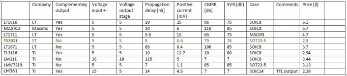
Comparators and CMRR and SVR
Started looking at comperators, and was shocked that the ones I use cost more than 6 USD ... MAX913, which I got a bunch of samples of for free
Anyway made a small comparisson, see below.
I have tried to use LT1711 which is faster, but it also strikes me how much more current some of these comparators in question draws. This I think have an impact on the voltage regulator used. In my designs I just uses a transistor and diode to get from Vcc/Vss to +5V/-5V.
At higher voltages of Vcc/Vss it matters if you draw 15 mA switched at 250 kHz or only a few mA. (at least using the LT1711 got both comparator and regulator a lot hotter). Also using the same +-5V supply for an input buffer and a integrator (opamp), it can have an impact on the performance of these.
Therefore I'll definetly try out TS3011 or LMV7219.
But looking af the difference of CMRR values and PSRR/PSV I'm starting to wonder again which is the best. Her the MAX913 I use seems quite superior!
But what does that mean .... how much more distortion does it relate to??
A lower PSRR will of course require a better regulation, to obtain the same result, but how important is this? It of course depends on the oveall design, how much feedback etc.
With regards to CMRR, I would think it has little impact when one of the input terminals are tied to GND.
Any reflections?
Best regards Baldin
Attachments
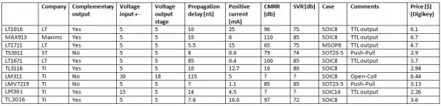
List updated.
Thanks Baldin this should be useful for people confused about comparator selection..
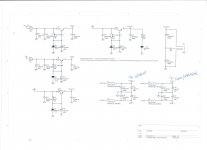
PSRR
Thinking about PSRR, I'm also thinking whether the scheme I use is efficient and optimal wrt. space used on the board and the component price.
I use the same regulator for both an input opamp and for the comparator. But to separate these I'm using some small 0805 beads to make separate filters on the output of the regulator.
See drawing.
Any thoughts on this?
Best regards Baldin
Attachments
- Status
- This old topic is closed. If you want to reopen this topic, contact a moderator using the "Report Post" button.
- Home
- Amplifiers
- Class D
- Differential phase splitter with level shift capability