Hi, I am hoping to prevail again upon the great help I have received in the past from this board.
My new problem is a 4 channel digital amp – 2 channels being out. The source of the problem was careless removal of the bridged sub it was driving. The output was shorted, it would appear that the protection was not sufficient.
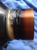
Now the amp seems to deliver full output from channels 3 & 4, when reconnecting the sub ( which blew on reconnection to faulty amp) a largish spark appears – protection kicks in and channels 1 & 2 stop until the connection is removed. I tried a second speaker and it dispatched that instantly.
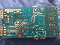
This amp has a design such that it is very difficult to work on in it’s case – the heatsink is the case, so powering up and testing is a problem without an involved removal/install process. Basically the underside of the PCB is inaccessible while the heatsinks are in operation.
So if I can diagnose without powering up all is the better. I suspect that the output transistors may have failed. Was hoping given the symptoms some guidance could be given on the best plan of attack for remedying the problem. I am not very good at this stuff so please do not assume too much knowledge . Thanks for any help given.
My new problem is a 4 channel digital amp – 2 channels being out. The source of the problem was careless removal of the bridged sub it was driving. The output was shorted, it would appear that the protection was not sufficient.
Now the amp seems to deliver full output from channels 3 & 4, when reconnecting the sub ( which blew on reconnection to faulty amp) a largish spark appears – protection kicks in and channels 1 & 2 stop until the connection is removed. I tried a second speaker and it dispatched that instantly.
This amp has a design such that it is very difficult to work on in it’s case – the heatsink is the case, so powering up and testing is a problem without an involved removal/install process. Basically the underside of the PCB is inaccessible while the heatsinks are in operation.
So if I can diagnose without powering up all is the better. I suspect that the output transistors may have failed. Was hoping given the symptoms some guidance could be given on the best plan of attack for remedying the problem. I am not very good at this stuff so please do not assume too much knowledge . Thanks for any help given.
Attachments
First, don't ever connect or disconnect anything when any amp is powered up.
Second, always measure for DC at the output before connecting any speaker. It could be that you have the full DC supply voltage across the output, for example.
What kind of measuring equipment do you have? Multimeter at least?
Second, always measure for DC at the output before connecting any speaker. It could be that you have the full DC supply voltage across the output, for example.
What kind of measuring equipment do you have? Multimeter at least?
Last edited:
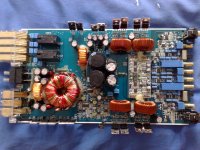
Agreed.At the very least you have some blown output devices (the FET pairs next to each output inductor). Check them for shorts. Hopefully nothing blew on the modulator/driver daughter board.
I'm going to assume that this car amplifier is an open-loop, "compare the audio against a triangle and drive FETs with that" amplifier, like every other one I've looked at.
Assuming this is the case, for each blown channel...
- Remove both FETs.
- Figure out which FET is the low side one, and put a jumper between source/drain in that part location.
- Grab an oscilloscope. Make sure that both high side and low side gate drive waveforms are present, don't overlap, have a sensible switching frequency and amplitude, etc.
Thanks for the input guys, as an amateur I did not want to go wrecking things I didn't have to. I have removed all of the mosfets - 2x IRF540 and 2x IRF9540 on channels 3 & 4. No oscilloscope only the humble multimeter, now I have confused myself in the past but from what I can tell the two P types have similar readings on the diode test reading around 1000 & 1100 and seem to turn off on when bridged/drained
The N type have readings of 210 & 34, they will also turn off when drained - I am wondering if the low reading is indicative of a problem. If this is the case - is it best to replace all N & P's ??
Should I be looking elsewhere or is the first step to order some replacements bung them in and hope for the best?
Oh; don't do the "short source/drain together" test that I mentioned above. That test is only for when both output FETs are N-channel, with the high side FET driven by a bootstrapped driver.
If you can, I'd really suggest finding someone with an oscilloscope. You'll want to look at the gate drive waveforms and make sure they're OK, and you can't do that kind of work with a DMM.
If you can, I'd really suggest finding someone with an oscilloscope. You'll want to look at the gate drive waveforms and make sure they're OK, and you can't do that kind of work with a DMM.
Without seeing a detailed circuit it's guesswork.
Are there any diodes across the FET's that could have failed ?
You could also trace the gate of each FET back and see what the FET driver is. You are really looking for any parts that could allow a significant current to flow in the event of a G-S, G-D failure. Anything isolated by a few hundred or even 10's of ohms of resistance is likely OK.
Can't really suggest anything more on this I'm afraid.
 .
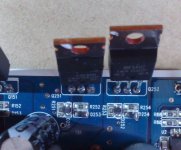
.That reading is in circuit on 200 setting for resistance and am guessing it is the driver circuit as the diode is connected to the FET and sits on the pcb. I have no schematics and can only photograph the pcb. The reason I am thinking it is the other mosfets is that I can measure resistance (then the meter will go open circuit) when I connect the probe to one of the failed outputs and an original FET.
These are the diodes I am measuring, all the gate diodes reading 4 ohms, no reading on any of the diodes such as d253, however on diode test they are showing around the 900 level. The exception is on one of the 9540 & and one of the 540 original FETs, which are very low almost zero - all are being meaured in circuit. Given that they are measured in circuit could it be a fault with one of the original FETS or the driver diodes or both?
Attachments
- Status
- This old topic is closed. If you want to reopen this topic, contact a moderator using the "Report Post" button.
- Home
- Amplifiers
- Class D
- Car amp fryer of voice coils