Hello there building up 2 x l25d amps. Not gonna worry too much about details other than to say that im having problems with my toroid.
No i had no choice but to use a 500va autotransformer that i aquired.
I have had this on the bench and well it fires up ok and runs and i have +-50v on the two outputs.
Now for some reason when i put it in the case (not touching any of the other parts) and hook it up to my two bridge rectifiers it keeps blowing my breaker.
sometimes i actually stays powered up for say 2 seconds then blows my 10 amp fuse. I have fitted 2 220nf caps across the two outputs but im sure this is not an issue as this is designed for noise supression i think according to the amp schematic i looked at.
Anyhows im just looking to find out if there is something obvious that i am missing. I am very sure that it doesnt need a soft start as it runs ok on the bench. Although i may need it when i get the caps on.
I will try to update with pics tommorow but just cant seem to keep the power from tripping when its in its box. I have tried many ways to power it up and well on its own is the only way ive managed so far.
Any help well appreciated.
If is really an autotranformer stop using it, you are in danger of electric shock! Use a normal transformer and ask Google about differences between a transformer and an autotransformer.autotransformer
 an autotransformer does not isolate the secondary from the primary since it has only a single winding. It is unwise to use such a device to power an amplifier circuit because non-isolation from the mains is very dangerous and can cause death to you or some other unsuspecting person.
 Please use an isolated supply either a mains line isolation transformer or SMPS.
Autotransformer ?
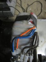
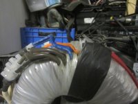
Right so here are a few pics. Now the reason i question the ability to safely use this is because unless i am mistaken there seem to be separate coils but still linked like an auto transformer.
THIN ORANGE = 240v ac
THIN BLUE = 240v ac
THIN REDS = Joined as input is duel 115v
THICK BLACK = 50v ac
THICK BLUE = 50v ac (Joined to thin blue as autotransformer common neutral)
THICK BROWNS = Joined as output is duel 50v to form common
So to me it looks like the thick side is separate from the thin, except for it to work the two netruals must be connected.
So if that is the case then i should be able to isolate right.....anyways any ideas with this as its the only one i got atm.
Attachments
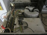
Measure with an Ohm meter to find out if the windings are electrically insulated. If it came out of an old amplifier it is most likely a transformer. It looks like a standard toroidal transformer with two 115V primary windings that would be connected in series for 230VAC mains. It is likely from its size that it may need to be slow started. Toroidal transformers suffer from magnetic memory. Because it has a solid core and there is no gap as opposed to laminated EI type cores, generally the leakage flux is very low and the flux density is higher. If you take a non-magnetic screw driver and place it on a magnet for a while it will remain magnetic for a short time after removing it from the magnet. Large toroidal cores will do this as well. If power is removed at the peak of the input AC cycle, the core will remain magnetized in that polarity. When power is re-applied and it happens to be near the peak of the same polarity that it as was removed the core can be driven into flux saturation and then the mains voltage source sees an impedance that is only the small DC resistance of the primary winding resulting in a surge current tripping a breaker or blowing a fuse. To prevent this, a resistor is placed in series with the primary for a few cycles to re-orient the polarity of the core and then the resistor is shorted with a relay. This is the basics of a slow start circuit.
Soft Start
Yes i was looking into soft start, but was just confused as it seems to power up fine on the bench but when connected to the bridge rectifiers then it trips.
Now the issue is it says auto transformer on the side, havent got the make details to hand, but im gonna have to go test it again, as well if i dont connect the two netral lines together and try it as a normal toroid.
Im gonna have to get back to you after more tests, im thinking im not quite getting the config for the wiring right. Gonna check whether im connecting to neutral when i dont have to.
Back soon.
Measure with an Ohm meter to find out if the windings are electrically insulated. If it came out of an old amplifier it is most likely a transformer. It looks like a standard toroidal transformer with two 115V primary windings that would be connected in series for 230VAC mains. It is likely from its size that it may need to be slow started. Toroidal transformers suffer from magnetic memory. Because it has a solid core and there is no gap as opposed to laminated EI type cores, generally the leakage flux is very low and the flux density is higher. If you take a non-magnetic screw driver and place it on a magnet for a while it will remain magnetic for a short time after removing it from the magnet. Large toroidal cores will do this as well. If power is removed at the peak of the input AC cycle, the core will remain magnetized in that polarity. When power is re-applied and it happens to be near the peak of the same polarity that it as was removed the core can be driven into flux saturation and then the mains voltage source sees an impedance that is only the small DC resistance of the primary winding resulting in a surge current tripping a breaker or blowing a fuse. To prevent this, a resistor is placed in series with the primary for a few cycles to re-orient the polarity of the core and then the resistor is shorted with a relay. This is the basics of a slow start circuit.
Hi - I have a basic question about transformers. When a x-former has dual primary inputs (115v each), these are normally connected in parallel to maximize x-former current output on the multiple secondary taps. Is that a correct statement? Is it also fair to say that if only a single primary winding were used, you'd essentially get about half the current on the secondaries? I just want to make sure these primaries can be connected in parallel for standard operating configurations.
") ) It's been a long, long while since my basic electronics courses, and just want to make sure I don't melt my spanky new toroidal.)
) It's been a long, long while since my basic electronics courses, and just want to make sure I don't melt my spanky new toroidal.)Yes, I'm pretty sure that you're right. The reason that there are two is of course so that in a country where the mains voltage is 230V they can be run in series.Hi - I have a basic question about transformers. When a x-former has dual primary inputs (115v each), these are normally connected in parallel to maximize x-former current output on the multiple secondary taps. Is that a correct statement? Is it also fair to say that if only a single primary winding were used, you'd essentially get about half the current on the secondaries? I just want to make sure these primaries can be connected in parallel for standard operating configurations.
One of the first things I do if / when I get an amp (or a computer) which has a switch for either is fire up the hot-glue gun and make sure that it can't be switched easily. I'm in New Zealand where we have 230V and I'll never forget when a pupil at the local high-school switched all of the computers to 115V last thing before going home. Apparently there were lots of expensive bangs the next morning when the first computer class of the day started. (It was a while back, before PSUs had all of the safety stuff the newer ones have.)
Hello just an update, seems that this is indeed a standard toroid, upon separating the two blue wires she does indeed have two separate windings in and out.
I have started a thread about thermistors as atm i need to get a suitable soft start to cope with the toroid, rectifiers and caps.
I have started a thread about thermistors as atm i need to get a suitable soft start to cope with the toroid, rectifiers and caps.
Colour coding for transformers is not standardized. I would always get the multimeter out with any new transformer to check the windings connectivity on resistance, and once the primary is energized I'd use ac volts to check the secondaries and their relative phasing.
Powering up a transformer without understanding it is not a great idea!
Powering up a transformer without understanding it is not a great idea!
- Status
- This old topic is closed. If you want to reopen this topic, contact a moderator using the "Report Post" button.
- Home
- Amplifiers
- Class D
- L25D Toroid