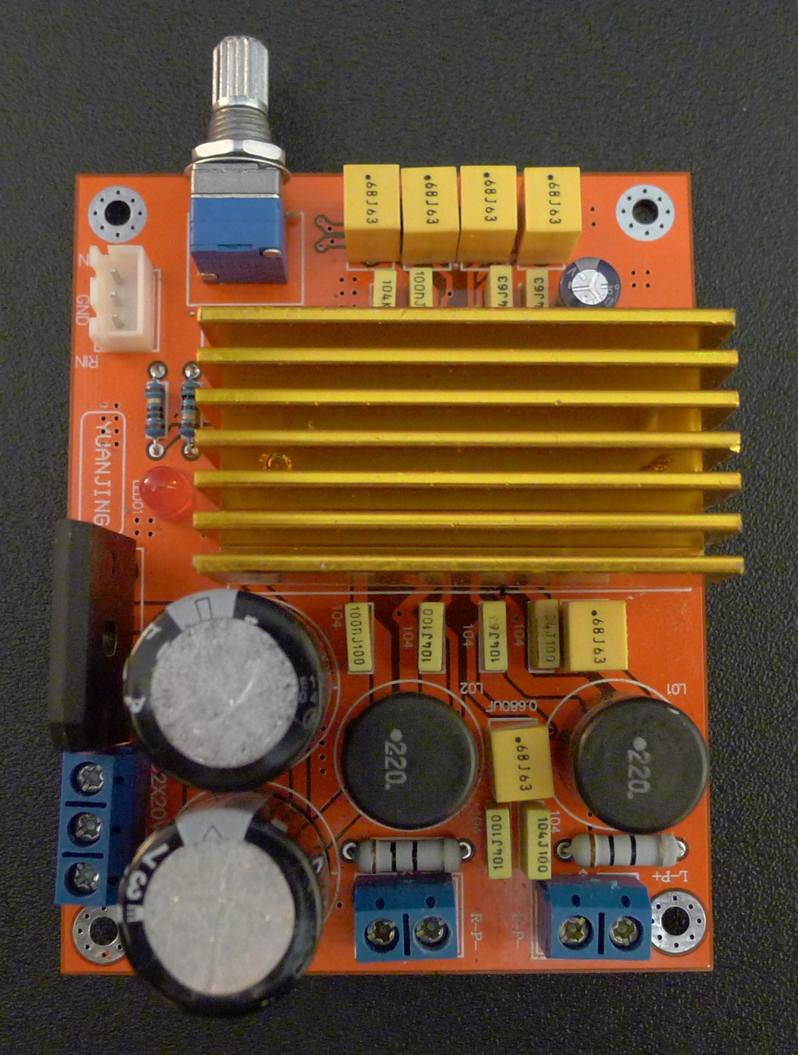
I decided I would buy some of the inexpensive TDA8920 boards from Ebay that zog66 previously described:
http://www.diyaudio.com/forums/class-d/170059-inexpensive-yuanjing-tda8920-board-ebay.html
Since I am supposed to be 'an expert' on switched power amps I figured I would be able to get the boards going, despite ljm_ljm's admonition about Yuanjing being a brand to avoid.
When I fired the first one up I immediately noticed a 50KHz oscillation on the output, which varied with the setting of the gain control. Did the usual things -- bypassed the poly caps with ceramics, etc -- tried to place some solid alternate earth bars over the PCB -- no luck. Figured it was probably a resonance in the LC output filter (22uH and 0.68uF damped by a 10 ohm/ 100n combo) but simply optimizing the RC damping network didn't control the oscillation.
Tried to put the amp into Bridge BTL mode. That oscillated to the point of the chip getting quite hot. Anyway, at some point in my testing I managed to blow up one of the TDA8920 -- they are very sensitive to not having both supply rails applied at once.
Unbolting the heatsink I noted that there was a mica washer -- far too thick, IMO -- glued to the TDA8920B by white silicone adhesive. There was no heat compound on the top of the mica, to help couple to the heatsink. And the silicone adhesive between the chip and the bottom of the mica slab is stuff you would normally put on bathtubs, not silicone grease... Sigh...
So I ordered a couple of L20-D boards of ljm_ljm's design, and put these Yuanjing units aside. But I can't get out of my mind that I ought to be able to get them working. Sigh... Once and injuneer always an injuneer, I guess... Has anybody any ideas where I should be looking?
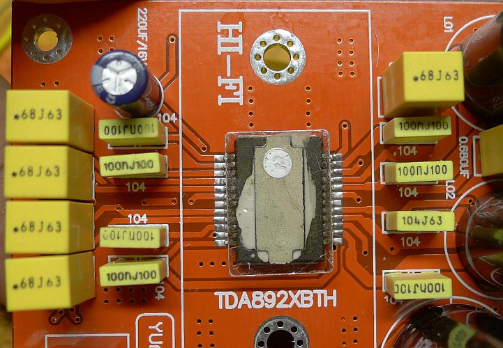
I purchased a new NXP TDA8920 from Mouser (USA), dug out my surface-mount toolkit, and soldered it in. I used a Thermalloy flexible heat-conductive washer rather than the original mica. I also changed the zobel damping resistors to the recommended 22 ohm, rather than the 10 ohm in the board.
The biggest change was to swing the 680nF capacitor at the top of the close-up image (above) around 90 degrees so that it connected to the output ground 'plane' rather than a plane more closely connected with the inputs. Removed the bypass capacitor there to free up the hole, and put two 330nf ceramic bypass capacitors under the board on the two out put rails.
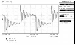
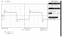
Here are the waveforms from my much-worn and elderly HP54522A")
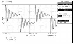
With a 20 V p-p square wave you can clearly see the output filter is relatively high Q. Without any load applied to an output, I measured with the correct 22 ohm zobel resistor and the 10 ohm which was in the boards when they arrived, and there was a marginal difference. You can see that the 22 ohm does provide better damping, although there is only a marginal difference. When an 8 ohm load is applied, the waveform cleans up, as you can see in the third attachment image.
I will try to get a BTL (bridged) configuration going too, and will report those results.
The biggest change was to swing the 680nF capacitor at the top of the close-up image (above) around 90 degrees so that it connected to the output ground 'plane' rather than a plane more closely connected with the inputs. Removed the bypass capacitor there to free up the hole, and put two 330nf ceramic bypass capacitors under the board on the two out put rails.
Here are the waveforms from my much-worn and elderly HP54522A
With a 20 V p-p square wave you can clearly see the output filter is relatively high Q. Without any load applied to an output, I measured with the correct 22 ohm zobel resistor and the 10 ohm which was in the boards when they arrived, and there was a marginal difference. You can see that the 22 ohm does provide better damping, although there is only a marginal difference. When an 8 ohm load is applied, the waveform cleans up, as you can see in the third attachment image.
I will try to get a BTL (bridged) configuration going too, and will report those results.
Attachments
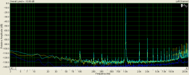
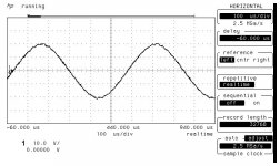
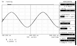
Here, for completeness, is a 20V p-p sinewave with no-load and 8 ohm loads applied. This is a single-shot storage, so you can see the dithering of the PWM converter. Remember that although the waveform imperfections look none-too-good, the PWM corrections are being applied at a very high frequency, above 200KHz. The amplifier actually sounds fine now...
Attachments
just to let you know..
the circuit is almost same like the app in TDA datasheet...
i tried also some mods...
1. changed input to dc coupling (removed .68 caps)
2. changed the 5k6 to 430 r in input
3. changed the cer.caps (330p ) to 220p FKP (WIMA) -> much better
the circuit is almost same like the app in TDA datasheet...
i tried also some mods...
1. changed input to dc coupling (removed .68 caps)
2. changed the 5k6 to 430 r in input
3. changed the cer.caps (330p ) to 220p FKP (WIMA) -> much better
Last edited:
Just confirming it is the Zobel damping network which needs to be adjusted to stop the 50KHz (approx) oscillations with no-load connected to these amplifiers.
The amplifiers which were supplied to me from Hong Kong had 680nF capacitors in the output filter (with 22uH inductors) rather than the 470nF capacitors recommended in the TDA8920 data sheet. Consequently the currently installed 100nF and 10 ohm resistor do very little to damp the Q of the output filter. I changed mine to a 220n and 22ohm series resistor configuration. This worked perfectly, and damped all remaining tendency to oscillate under a no-load condition. Be careful to use at least a 2W resistor in this position, especially after increasing the cap to a 200nF
ps: unsoldering the 100n zobel cap position is very difficult as the ground planes are hard to desolder. I suggest soldering an additional 100nF across the bottom of the board rather than trying to remove the caps already soldered in place
Last edited:
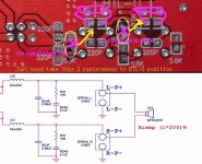
For completeness, I finished testing the boards in BTL mode, having found the instructions posted by leau2001 in another thread (for a different style Yuanjing board) (see attachment below).
Both the Yuanjing boards I tested worked well in BTL after these instructions were applied. Both were stable, both having been modded as described in previous posts. The heatsinks stayed below 100 degrees centigrade when tested with the largest undistorted output sinewave possible, about 50V p-p (bridged) across my 8 ohm resistive load (27.5V-0-27.5V supply). The board stayed within 10 degrees of the heatsink temperature. That power level is just above 40 watts, but you will get the 'rated' 70W if you push the distortion to 10%. I tend to stay below the level at which the PWM digital artifacts occur. Any half-decent speakers can numb my ears from hearing any artifacts above a 40W power level
So I am happy with my amplifiers now. If you don't do any mods to yours, make sure you remove the heatsink, scrape off any Silastic, install silicon grease, and preferably also a high-efficiency thermal washer
.
Attachments
hozone, the safest way is to put a low-voltage 1KHz square wave into the input of the amplifier, not enough to drive it very hard, and look at each of the outputs with your oscilloscope. If you see "ringing" at the rising and falling edge of the square wave that means the circuit is not critically damped. A lot of oscillation means the circuit is unstable.
Better analog scopes will be able to trigger on the higher frequencies at the edge of your squarewave, and allow you to measure the period of the HF waveform, and figure out the instability frequency. Never drive your amplifier with supersonic input frequencies while there is any ringing on the edge of your squarewave.
I hope that helps
.
hozone, the safest way is to put a low-voltage 1KHz square wave into the input of the amplifier, not enough to drive it very hard, and look at each of the outputs with your oscilloscope. If you see "ringing" at the rising and falling edge of the square wave that means the circuit is not critically damped. A lot of oscillation means the circuit is unstable.
Better analog scopes will be able to trigger on the higher frequencies at the edge of your squarewave, and allow you to measure the period of the HF waveform, and figure out the instability frequency. Never drive your amplifier with supersonic input frequencies while there is any ringing on the edge of your squarewave.
I hope that helps
.
thank you,
let's say a 1Vpp square?
i have to scope the output of the board with a dummy load, a speaker load, or simply using the scope?
thank you,
let's say a 1Vpp square?
i have to scope the output of the board with a dummy load, a speaker load, or simply using the scope?
1V p-p will be just fine, although you will find the stability changes with level. But that's a discovery waiting in the wings to keep life interesting
It will behave very differently into an open circuit, a resistive load, and a speaker (which is often regarded as an inductor and resistor in series). I just posted a small simulation file so you can plug in the values to MultiSim, and double-check what your scope is telling you. See the topic at:
http://www.diyaudio.com/forums/clas...tput-filter-designs-sure-tda7498-example.html
: Enjoy!
Good thread!
I bought one of these - at high power the silicon bathroom sealant liquifies and leaks out between the chip and heatsink, so I too cannot recommend it as a decent thermal compound.
I also have the 50khz oscillation, it comes as standard I guess, hopefully after the recommended mods in this thread I'll have something half decent.
- Status
- This old topic is closed. If you want to reopen this topic, contact a moderator using the "Report Post" button.
- Home
- Amplifiers
- Class D
- Yuanjing TDA8920B board unstable - 50KHz