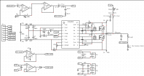
hello there i just finished my schematic and wanted to know if everything is kinda correct to finished my PCBoard.
the mosFET are irf540N
Vds 100V
Id 33A
Rds on 44mohm
trise 35ns
Qg 71nC
all diode are MUR120
Cosc and Ccomp are 1nF
output filter is left to be done.. i think im gonn put the one from typical schem.
i have put many pot for optimisation cause i had some probleme with current sensing and feedback with my breadboard attemps ( i know, i was on breadboard.. but anyway) and also to adjust the self oscillating frequency
also if you have more PCB layout considarration than AN-1138 from irf tell me please, im gonn put the pcb screenshot after comments") thx everyone !
thx everyone !
the mosFET are irf540N
Vds 100V
Id 33A
Rds on 44mohm
trise 35ns
Qg 71nC
all diode are MUR120
Cosc and Ccomp are 1nF
output filter is left to be done.. i think im gonn put the one from typical schem.
i have put many pot for optimisation cause i had some probleme with current sensing and feedback with my breadboard attemps ( i know, i was on breadboard.. but anyway) and also to adjust the self oscillating frequency
also if you have more PCB layout considarration than AN-1138 from irf tell me please, im gonn put the pcb screenshot after comments
thx everyone !Attachments
ight thanks! i've some torroidale ferrite core in my pocket right now.. when i was on breadboard i was using them and it was working not bad.. but ive no clue of what kind it is, i think im gonn buy the one you told me!
On my first attempt at a 2092 layout I naively just bought a power inductor. This got very hot, about 120 degrees ! Power inductors are not meant for class d.
The t106-2 is the proper core and doesnt get hot at all.
using gate buffer like a NPN ? or like another driver ( irs2110 or somethin like that) ?
also i changed the gate resistance.. 11.3V /10ohm = 1.13A = too much for the Ho output, i'll put a 47ohm
I would stick with 10R. Its not as simple as 11.3v/10r as you are essentially charging up the gate capacitance. The rise time is pretty quick so the current is not taken for long.
If you start putting large gate resistors in there you will get slower rise and fall times and risk shoot through.
yeah i know im charging a cap.. Ic = Io e^(-t/RC)
im not that dumb
So why do IR suggest 10R in their datasheets ?
HO drives IN1,2interresting.. for HO you put Vb for supply voltage referenced to Vs ?
Vb is also on Vcc
And Vs is connected to GND
So, you take the same supply lines for this buffer as IRS uses, Vb, Vs for upper one, Vcc and Com for lower one, and you drive each buffer IN1,2 via resistor from HO and LO respectively. Source and sink I have connected together, going to gate resistor as it would if there were no buffers (I did it as a mod, after I had boards already made). Now you do need to drive this buffers instead of fets, but at >550kHz, IRS only gets warm, instead of super hot (with this kinda big gate charge fets)
- Status
- This old topic is closed. If you want to reopen this topic, contact a moderator using the "Report Post" button.
- Home
- Amplifiers
- Class D
- irs2092 schematic confirmation