Yes of course I know... but that's what my oscilloscope says... the speakers say hum...
I was just kidding , but you probably have some ground loop problem , Be sure to use a star ground , all grounds to one point at the PSU ( see my system picture in my previous post) I had a little hum in my 5 x L15d system in the beginning , when I wired the speaker grounds direct to the L15D boards . after I changed the speaker ground wiring directly to the star point at the PSU the system was totally quiet .
Cheers

Rens
well yes, but not because of the switching amp. you can't hear that freq. of several 100kHz. my hum if I would put it like that is because of not really good ground between computer, power outlet and amp and so on. with no signal, no cable on input, you can't hear anythingDo I get you right? Your speakers produce hum, too? I'll try to measure the SMPS's hum with some resistors, so without the hum from the amps. Doesn't anybody have similar experiences or some measurements?
Are threre any mods so solve it?
I know what you mean and I don'r really know the problem. I also know I'm not able to hear > 16 - 18kHz. But I can hear the hum from the speakers really good, and after I simply wired only one module and solved any possible loops, I have no idea instead. Is it possible, that the SMPS' s ripple / AC is too high and so the mosfets or other vomponents are oscillating?
I was just kidding , but you probably have some ground loop problem , Be sure to use a star ground , all grounds to one point at the PSU ( see my system picture in my previous post) I had a little hum in my 5 x L15d system in the beginning , when I wired the speaker grounds direct to the L15D boards . after I changed the speaker ground wiring directly to the star point at the PSU the system was totally quiet .
Cheers
Rens
Hi Rens,
So to make this clear for me

Your speaker ground goes both (first) to the common star ground and (then) to the minus binding post on the L15d.
I have some his that I would like to tackle, this is by far the easy way out.
Thank you
Peter
Noise
I wired my amp as described in post 47
http://www.diyaudio.com/forums/clas...d-irs2092-irfi4020h-200w8r-5.html#post2687712
That solved my ( modest) hum problem .
Dont think it will make any difference with noise . My amps have very little noise , only audible with the ear in front of my very sensitive Tannoys .
Cheers ,
Geniet van de oliebollen ! (Enjoy the Oil Balls!)
Rens
Last edited:
His , Hum or what
Hi Peter ,
Do you have noise ( Hiss) or hum in your system , I don't have a schematic of the l15D pro with DC protection , but have a pretty good idea how it is wired on the PCB and I think there will be a problem in a multi amp system on one PSU with this board .Do you have the schematic ?
Cheers ,
Rens
Hi Rens,
I use the L15d-pro. Just searched for the recommended wiring, as it is different because of the incorporated speaker protection.
So your solution will not work for me.
Oliebollen / appelflappen: we zullen er zeker van genieten!!
Groet
Peter
Hi Peter ,
Do you have noise ( Hiss) or hum in your system , I don't have a schematic of the l15D pro with DC protection , but have a pretty good idea how it is wired on the PCB and I think there will be a problem in a multi amp system on one PSU with this board .Do you have the schematic ?
Cheers ,
Rens
I think you could hear AC because its possible that is passes through amp and its not filtered out by LC, because freq of ripple could be in audio rangeI know what you mean and I don'r really know the problem. I also know I'm not able to hear > 16 - 18kHz. But I can hear the hum from the speakers really good, and after I simply wired only one module and solved any possible loops, I have no idea instead. Is it possible, that the SMPS' s ripple / AC is too high and so the mosfets or other vomponents are oscillating?
you would want to have smps dead silent or at least anything far beyond audio range
Hi Rens,
The schematics of the wiring.
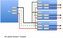
I use a connexelectronics smps500r to feed them.
My grounding is floating as I have no grounding in my sockets.
Peter
Try to connect each amp ground ( green ) seperately to the PSU GND and also the speaker minus directly to the PSU GND. I Use a M6 screw with crimp connectors as my star point as shown in the picture .
Hope this helps .
Cheers ,
Rens
Attachments
D
Deleted member 148505
Also adjacent channels should be set with different self oscillating frequency. (according to Iraudamp7s reference design)
"In relative terms, interference between channels is most significant if the relative frequency difference is within the audible range.
Normally, when adjusting the self-oscillating frequency of the different channels, it is suggested to
either match the frequencies accurately, or have them separated by at least 25kHz"
Hi Rens,
Thank you for the input.
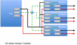
What about this solution to keep minimal wiring.
Hi Peter Henk ,
You can give it a try , but I dont like the shared supply wires either , I would go for seperate for each amp . I build a lot of amps and had a lot of ground loop problems in the beginning ( many years ago ) so started building with seperated supply and ground wiring in multy amp systems a couple of years ago and never had any problems since .
The speaker wiring might work as you drawn it , if not ground your speakers at the star ground . I asume the DC protection switches the High side of the signal .
I must also advise you to use high quality interconnects between class D amps and your sources . I had some very strange noises from my speakers when I just started with class D amps and used those cheap thin RCA Red/White cables that come in your CD player packaging .was all gone when I bought some dencent Interconnects .
If you still hear "His" or whatever with no signal , short the inputs at the boards and see if the problem is gone .
Good luck ,
Cheers ,
Rens
Hello again,
the picture describes the measurement between loudspeaker+ and GND without signal-in, as I described before
It's a clear sine, everything is checked twice but I can't find the reason, why I got such a signal with 400kHz and 2,5V out...
All power cables are twisted, there is no longer cable then about 12cm, GND is although put together. As I have sandwich-mounted the amps I'm not sure, if they disturb each other...
edit\\
I built out an amp, same result, so sandwiching the amps seems to be OK for them...
the picture describes the measurement between loudspeaker+ and GND without signal-in, as I described before
An externally hosted image should be here but it was not working when we last tested it.
It's a clear sine, everything is checked twice but I can't find the reason, why I got such a signal with 400kHz and 2,5V out...
All power cables are twisted, there is no longer cable then about 12cm, GND is although put together. As I have sandwich-mounted the amps I'm not sure, if they disturb each other...
edit\\
I built out an amp, same result, so sandwiching the amps seems to be OK for them...
Last edited:
Hello again,
the picture describes the measurement between loudspeaker+ and GND without signal-in, as I described before
An externally hosted image should be here but it was not working when we last tested it.
It's a clear sine, everything is checked twice but I can't find the reason, why I got such a signal with 400kHz and 2,5V out...
All power cables are twisted, there is no longer cable then about 12cm, GND is although put together. As I have sandwich-mounted the amps I'm not sure, if they disturb each other...
edit\\
I built out an amp, same result, so sandwiching the amps seems to be OK for them...
Just carrier residue , nothing to worry about , most class D amps have this residue , see post 1 of this thread , 3rd picture , the carrier is superimposed on the sine wave of the output signal . And being 400khz , not audible .
Cheers ,
Rens ( already in 2013
)Interference ?
Good remark Jan ,
You made me thinking , I have no audible problems with this and read allot about it . So I measured my carrier frequencies today and they are well within 25 kHz of each other . LF and RF are just 4 kHz apart and the rest of the channels within 10 kHz . If I use the amp in Stereo mode ( 2 channel RF and LF ) the sound stage is very precise and dolby digital is just stunning , enjoy it every day .
What I understand from the papers is that the THD is about 10 times higher at low power and the AM intermodulation and EMI are much higher if you synchronise the clocks . I have noticed that the new CxD250-HP from Christi at Connexelectronic has the ability to synchronise the clocks , so lets have some discussion here

It's quite easy to ad an external clock to my 5 L15D's just 5 resistors and 5 capacitors and a clock . Does it make sense ???
Cheers ,
Rens
And I'm drinking a nice Chardonnay
Also adjacent channels should be set with different self oscillating frequency. (according to Iraudamp7s reference design)
"In relative terms, interference between channels is most significant if the relative frequency difference is within the audible range.
Normally, when adjusting the self-oscillating frequency of the different channels, it is suggested to
either match the frequencies accurately, or have them separated by at least 25kHz"
Good remark Jan ,
You made me thinking , I have no audible problems with this and read allot about it . So I measured my carrier frequencies today and they are well within 25 kHz of each other . LF and RF are just 4 kHz apart and the rest of the channels within 10 kHz . If I use the amp in Stereo mode ( 2 channel RF and LF ) the sound stage is very precise and dolby digital is just stunning , enjoy it every day .
What I understand from the papers is that the THD is about 10 times higher at low power and the AM intermodulation and EMI are much higher if you synchronise the clocks . I have noticed that the new CxD250-HP from Christi at Connexelectronic has the ability to synchronise the clocks , so lets have some discussion here
It's quite easy to ad an external clock to my 5 L15D's just 5 resistors and 5 capacitors and a clock . Does it make sense ???
Cheers ,
Rens
And I'm drinking a nice Chardonnay
Some good news and some bad news here.
Good news first - it functions at 35V +/-

See that little blue light? Beautiful.
All that was necessary was swapping out the resistors as noted in the quoted post.

Now, on to the bad news. After removing, modifying, and rewiring the amp board in the one amplifier, I turned power on and POOF. Smoke.I accidentally wired DC+ to the wrong terminal on the board, and it fried something on both boards. The power supply rectifier/filter board was easy enough to fix - remove burnt traces and replace with thin wires. The amp board is another story entirely. I fear I may have burned up the opamp, rendering it useless.
There are no obviously burned traces on the PCB or components, and yet it does not function, and the pretty blue light does not function.
Anyway, that's a problem that is simple enough to solve by buying a new amp board, replacing the resistors, and not wiring incorrectly. This post is more to announce to everyone that it is possible to swap resistors and operate at lower voltage.
Now here's an album of the project so far: Photo Album - Imgur
Guys, i got 2 L25D boards, and i want to know if this modification also will work whit this board. Iw ant to run the amp whit +-35v
- Home
- Amplifiers
- Class D
- My design L20D IRS2092+IRFI4020H 200W8R