Yeah. It's calling to me too.....
I still think LJM's L25d and hien.t.nguyen's L25de is pretty cool, I just need to decide which to use. either way +/-70V and 250W is calling to me
 After reading pages of this thread I decided to order the ljm designed L25D version from zoe. I just like to have the extra headroom. I'll be driving it with a linear PSU at +-70v. Should be interesting to hear how it sounds.
 Actually, I might just swap out all of the 22uF 25V caps while I am at it with Elna Silmics. There are six per board. I may also order some 22nF MKP caps to parallel across CP1 on each board.
I will have to check when I get home whether the buffer caps in the L20D are actually 470uF 100V (per reference design) or 100uF 80V (per board markings). I think I will sub them with 470uF 50V Nichicon KZ caps.
I can't seem to find a good replacement for the 1nF ceramic caps (C2,C4,C6,C7) since they are so small, so I may just leave them in place. I was trying to find a comparable WIMA cap, but they all seem to be much too large.
R2 and R7 will probably be swapped with 1% Vishay/Dale resistors of the appropriate values.
stick witht upgrading the input and buffer caps , the rest won't give you any improvement (in sound )
.Cheers ,
Rens
I have one of these Sure Electronics class D amps that I have not fired up yet. Not trying to de-rail this thread by introducing another design, but was curious if anyone has both and done any serious comparison to the L25D by ljm. They both use the same IRS2092 chip and output devices, so was interested on any comments about it. I need to get this on my bench and see what it sounds like. I will be operating it with 65v rails.
Nice. Very nice man cave you have there.Doctordata - The comments about your speaker protection peaked my interest too. During the test after the mods, you did find the turn off time to be proper? I am not sure how fast the time really is, 1S or shorter? I have been pondering the protection scheme for some time. The bus pumping phase shifter of your is quite nice too! I planned on using cristy's BIPS module to offer the nice finished look of the jacks, and offer some line driver capabilities too.
Overall it sounds like you put your system through the ringer regarding testing. Its nice to know the ebay speaker protection circuit actually do work.
My multichannel setup would be for home theatre, driving a total of 8 full range speakers. The sub would probably be qty2 L25 bridged. Just cause I'm anal about commonality of looks and parts, I would probably use all L25 modules. My main speakers are 93db too and cannot wait to really push them hard. I have an antique onkyo reciever only "claiming" 60Wx2 in stereo mode. In multichannel it is pretty poor for my setup. My whole system is made up of athena audition series, not great but a really good speaker for little money.
Linky here
My Man Cave - Home Theater Forum and Systems - HomeTheaterShack.com
Actually, the filter caps on that particular board are high quality Rubycon electrolytics. I have the identical board and the pcb along with the build quality is first rate. I seriously doubt they would fail (unless pushed beyond their 80v rating), and start a fire.u should replace the caps in the ps board.
Not. And what do you base this knowledge on?the big black ones they are fakes just random sized caps pulled out of other electronics.
Not. And what do you base this knowledge on?
cut the tops off the caps and the real maker of each cap will be reveled . the tops being the fake plastic disk ontop.
cut the tops off the caps and the real maker of each cap will be reveled . the tops being the fake plastic disk ontop.
Nothing surprises me anymore and I would love to see a picture of those caps "without makeup"...
Nice pics of your project so far. Excellent job!Some good news and some bad news here.
Good news first - it functions at 35V +/-

See that little blue light? Beautiful.
All that was necessary was swapping out the resistors as noted in the quoted post.

Now, on to the bad news. After removing, modifying, and rewiring the amp board in the one amplifier, I turned power on and POOF. Smoke.I accidentally wired DC+ to the wrong terminal on the board, and it fried something on both boards. The power supply rectifier/filter board was easy enough to fix - remove burnt traces and replace with thin wires. The amp board is another story entirely. I fear I may have burned up the opamp, rendering it useless.
There are no obviously burned traces on the PCB or components, and yet it does not function, and the pretty blue light does not function.
Anyway, that's a problem that is simple enough to solve by buying a new amp board, replacing the resistors, and not wiring incorrectly. This post is more to announce to everyone that it is possible to swap resistors and operate at lower voltage.
Now here's an album of the project so far: Photo Album - Imgur
I'm certainly not naive to believe there are no fake components being used on all matter of boards from Asia or other places. But why would someone go to all the trouble of producing a super quality board and then place second rate, or inferior components on it? Profit you say...cut the tops off the caps and the real maker of each cap will be reveled . the tops being the fake plastic disk ontop.
Even in China it's in no ones best interest to build inferior parts just to save a couple nickels. We're living in the internet age where information travels in milliseconds not weeks. Word gets around real fast about bad products - and good. If these caps were know to cause fires - even anecdotally - the manufacturers reputation would be at risk and board makers would find other suppliers - real fast.
But I'll take you at your word and the next time I order any e-caps I'll order an extra one for purposes of destroying it just to identify the real manufacturer.
Can you post a picture of one with the top removed revealing the manufacturers name?
Last edited:
I'm certainly not naive to believe there are no fake components being used on all matter of boards from Asia or other places. But why would someone go to all the trouble of producing a super quality board and then place second rate, or inferior components on it? Profit you say...
Even in China it's in no ones best interest to build inferior parts just to save a couple nickels. We're living in the internet age where information travels in milliseconds not weeks. Word gets around real fast about bad products - and good. If these caps were know to cause fires - even anecdotally - the manufacturers reputation would be at risk and board makers would find other supplier - real fast.
But I'll take you at your word and the next time I order any e-caps I'll order an extra one for purposes of destroying it just to identify the real manufacturer.
were not talking a few nickles 10kuf 80v 105c caps arent cheap. $7 each x6 per board thats $42 on caps on your $32 ebay item.
Well I'm sure anyone building these boards is buying the components in bulk - whomever the manufacturer is, so the piece part cost is much lower. I didn't buy mine for $32. It was more like $48 I think.were not talking a few nickles 10kuf 80v 105c caps arent cheap. $7 each x6 per board thats $42 on caps on your $32 ebay item.
However, you've piqued my interest sufficiently enough so now I'm going to investigate further this particular Rubycon 10,000mfd 80v e-cap.
I trust my relationship with my preferred eBay vendor whom I have purchased hundreds of dollars worth of parts, kits and pre-assembled modules from. None of which I've ever had any issues with - either quality-wise, or performance-wise. If anything, and it turns out these caps are fake I would be surprised. He may be unwittingly 'taken' too. I hope not.
I went and opened up my amp to check the caps on my PSU module and luckily they are Nippon Chemi-Con electrolytics. So, at least from my vendor he is supplying Nippons and not Rubycons. I don't know how pervasive the Nippons are being counterfeit, but according to Google there are some out there. I'll let this thread get back on track. Apologizes.
I'll let this thread get back on track. Apologizes.After a weekend of hard work I finally "upgraded" my previous DIY amp and gave the L20d a try.
PSU is a connex SMPS800R @ +/- 60V (my speakers are closer to 5 than to 7 ohms, despite being rated at 8), I throw in a speaker protection board and turned on:
WOW, I have to say that's a little great amp board, with plenty of reserves for my 86 db/W speakers, the bass is rock solid, the highs airy, the stage a lot better than my previous TK2050.
The two boards heat up a lot more than my previous amp (more in a separated thread after some more listening sessions), meaning that efficiency is quite lover (but its a +/- 60V rail amp versus a +36V single rail amp, so it's not fair, and air temp is about 30ºC) but, after a night of listening I would say that's a very good implementation of the IRS2092 design.
Good job LJM, more news to come.
L20D or L25D will need to DC +-60 V DC voltage. In front can get the wiring diagram.
About your voltage AC22-0-22, indeed. TA2022 may be more appropriate it. It's very simple.
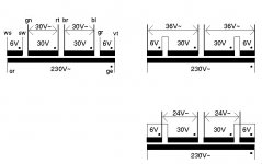
Hi Jim, I have also a powersupply question. I want to use 1 of my 2 highend toroidals (450 VA) for my L25D boards I recently bought. These are dual supply 36-0-36 and 6-0-6 output. When I add in series I achieve 42-0-42 and total DC about 59-0-59 Volts ... Would this work with the L25D ?
Thanks
are you sure the 36V and 6V outputs have the same current rating ? (same wires) typically, on such transformer, the power rating of each secondary is different.Hi Jim, I have also a powersupply question. I want to use 1 of my 2 highend toroidals (450 VA) for my L25D boards I recently bought. These are dual supply 36-0-36 and 6-0-6 output. When I add in series I achieve 42-0-42 and total DC about 59-0-59 Volts ... Would this work with the L25D ?
Thanks
6V output is typically for lower current needs, usually built with a thiner wire than the high power 36V output.
If wires don't have the same gauge on each secondary, if you put them in series, available power will be limited by the weakest.
In addition, the secondaries are probably center-tapped, 36-0-36 & 6-0-6, as you have described. Therefore, you can't put them in series and have access to the "center". You would get 48-0-36 or any other variant of 36-0-36-6-0-6. If the secondaries are isolated, then you could put them in series as you have suggested. However, alkasar's comment about the current rating is the overriding limitation.are you sure the 36V and 6V outputs have the same current rating ? (same wires) typically, on such transformer, the power rating of each secondary is different.
6V output is typically for lower current needs, usually built with a thiner wire than the high power 36V output.
If wires don't have the same gauge on each secondary, if you put them in series, available power will be limited by the weakest.
are you sure the 36V and 6V outputs have the same current rating ? (same wires) typically, on such transformer, the power rating of each secondary is different.
6V output is typically for lower current needs, usually built with a thiner wire than the high power 36V output.
If wires don't have the same gauge on each secondary, if you put them in series, available power will be limited by the weakest.
Here is an pic attachement with 30 V main voltage shown as example instead 36 in my case. The 6 V wires are definetly mentioned to inrease or reduce the 30 V. This toroidal is sold only for highend pursposes. 8 wires out. All same thickness.
Attachments
- Home
- Amplifiers
- Class D
- My design L20D IRS2092+IRFI4020H 200W8R