I am done with the reverse engineering to cross-reference L25 board.
For memory, the original IRAUDAMP7S is here, page 30
http://www.inductor.com/irf/iraudamp7s.pdf
L25D cross reference
http://img407.imageshack.us/img407/4201/l25dimplementationwithr.png
The design follows almost exactly IRF reference design.
some comments:
- The components values on the board follow the reference design, except for those to adjust according to power (in red in the schematic)
R7, R8, R17, R18, R12, R114, R115, R117, CP7, CP8
- pot P1 is not there. Instead, R11 is adjusted to 300R (resistor already sold on board)
- The protection led signal is not implemented (R14, CSD1, FET2, R3, D1)
- There is an additional 15V Zener, not on the schematic. Z? on board, already soldered. It is between pins 13 and 15 of IS2092
Sorry to bring this back from a long time ago, but I am looking to run an L25D at a lower voltage (35VDC +/-).
Would I be correct in interpreting the above post and others in this thread as meaning that it IS possible to run the L25D below the 60-70V +/- recommended range? If so, does it simply require changing a few resistors, as denoted by the reference document from IRF?
If I were at the beginning of this project, I wouldn't be asking this. I got all the way through construction and voltage testing before realizing my oversight. Someone help so I don't have to buy new amp boards?
Photo Album - Imgur
In Theory, yes, you should be able to adjust the resistor values and get it to run at 35V, but to my knowledge, I don't know of anyone who has done it..
Someone has to be first..")
Well the other option is to drop another $100 on new 50Vx2 toroids for the two amps. I think a couple dollars in resistors and some time is a better investment currently.
So, that entails:
R7 - Not listed in Table 5; 3.01K in Figure 33)
R8 - 100K
R17 - 33K
R18 - 4K7
R12 - 3K9
R114 - 220R, 1W
R115 - 10K
R117, R118 - 2K2, 1W
CP7, CP8 - Not listed in Table 5, presumably unchanged for lower voltage
The only other thing that is red in Figure 33 is FET1, which I assume will remain unchanged because its specs do appear to allow for 35VDC operation. Output power will be cut down considerably into an 8 ohm load.
Or I could swap the transformers out, get ~70VDC +/-, and enjoy not having to solder a bunch of components. Decisions, decisions.
Some good news and some bad news here.
Good news first - it functions at 35V +/-

See that little blue light? Beautiful.
All that was necessary was swapping out the resistors as noted in the quoted post.

Now, on to the bad news. After removing, modifying, and rewiring the amp board in the one amplifier, I turned power on and POOF. Smoke.
 I accidentally wired DC+ to the wrong terminal on the board, and it fried something on both boards. The power supply rectifier/filter board was easy enough to fix - remove burnt traces and replace with thin wires. The amp board is another story entirely. I fear I may have burned up the opamp, rendering it useless.
  There are no obviously burned traces on the PCB or components, and yet it does not function, and the pretty blue light does not function.
Anyway, that's a problem that is simple enough to solve by buying a new amp board, replacing the resistors, and not wiring incorrectly. This post is more to announce to everyone that it is possible to swap resistors and operate at lower voltage.
Now here's an album of the project so far: Photo Album - Imgur
D
Deleted member 148505
How is overall sound quality?Is it comparable to hifi power amps?
Sound quality is very subjective , but for me they sound very good ( L15D) .
I own several amps , vintage Dynaco Stereo 400 , Denon AV3808 and a Luxman 590 . for me the overall sound off the L15D's is a bit better than the Dynaco, much better than the Denon and equal at low volumes with the Luxman or a bit less with some music .the Lux gives some better image and more detail , at Higher volumes they are sounding better then the Lux .
Noise is quite a bit higher , but not noticable 20 cm from the speakers ( 93db/w Tannoys) In my home theater setup with Emotiva UMC-1 they are absolutely stunning ! Even some commercials on TV are fun to listen to!
Cheers ,
Rens
...
Now here's an album of the project so far: Photo Album - Imgur
Sorry to hear about the "accident"...
I have a couple of questions if I may:
#1 - Did you use a Par-Metal chassis? If not, which one?
#2 - Where did you get the PSU boards?
Thanks!
Hi
I have bought the l20d and ordered the Connex SMPS 800r aux 12 power supply. Now i am considering connecting a pair of VU meters to make my amp glow in the dark. Do you think it is possible use this from ebay: 2Pcs VU Panel Meter Warm Back Light + VU Driver PCB Board Stereo For Audio Amp | eBay ?
Thank u in advance
Hi guys,
reading the thread a long time I decided to build another L25D-amp. Cause just waiting for another SMPS from Christi, I got some time for optimizations. I decided for the SMPS800RE this time. Which components of the L25D should be replaced to get a better result?
It would be nice to summerize a sheet with all optimizations, so anybode has a overwiev what is possible by replacing which component.
Many thanks,
Stammheim
D
Deleted member 148505
Does this have a built in over current protection? Anyone tried shorting speaker outputs?(either intentionally or accidentally)
Hi LJM, Reposting my question...
Do I have to add over current protection?
D
Deleted member 148505
Here's my L25D running at +-53VDC, resistors adjusted to accommodate this voltage.
(Thin wires of second channel and amp layout are just temporary)
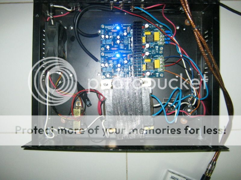
Very good sound stage and airy sound, but the treble/high sound is a bit dry. I think I might need to upgrade the input cap and add a tube buffer to achieve sweet sounding highs...
(Thin wires of second channel and amp layout are just temporary)
Very good sound stage and airy sound, but the treble/high sound is a bit dry. I think I might need to upgrade the input cap and add a tube buffer to achieve sweet sounding highs...
Last edited by a moderator:
Hey...
nothing to optimize?
Hi Stammheim ,
I changed the input capacitors ( of my L15D's ) with Silmic II's 22 uF/50V and increased the buffer caps to Panasonics 820uF/63V ( wich will fit on the PCB) Rs partno. 571521, wich should be fine with your rail voltage .
The difference is not huge but it's there . Highs are a little bit more sparkling and some more punch in the mid lows.
I'm loving these amps ,together with my Emotiva UMC-1 and 5 Tannoys and the (regulated) powersupply (A1000SMPS) from Connexelectronics it is a superb combination .I have a couple of much more expensive amplifiers , but did only listen to the LJM's for the last month because overall they sound the best .
Cheers ,
Rens
I actually think I am going to change out basically anything in the signal path except for the inductor at the output, since I am already modding my boards to accommodate 35V +/-
This list will include:
CP1 - 22uF
R2 - 330R
R7 - 3k01
C4 - 1nF
C6 - 1nF
I will probably follow doctordata's example and use Elna Silmics at the input. Would it be dangerous to put a film bypass paralleled with CP1, assuming I can find a way to fit it?
I may also swap the 470uF 100V caps for higher value, lower voltage, since they only need to handle 35V each. A nice 50V or 63V variety (also per doctordata) would work, correct? EDIT: as long as it is no more than 16mm wide
Last edited:
Actually, I might just swap out all of the 22uF 25V caps while I am at it with Elna Silmics. There are six per board. I may also order some 22nF MKP caps to parallel across CP1 on each board.
I will have to check when I get home whether the buffer caps in the L20D are actually 470uF 100V (per reference design) or 100uF 80V (per board markings). I think I will sub them with 470uF 50V Nichicon KZ caps.
I can't seem to find a good replacement for the 1nF ceramic caps (C2,C4,C6,C7) since they are so small, so I may just leave them in place. I was trying to find a comparable WIMA cap, but they all seem to be much too large.
R2 and R7 will probably be swapped with 1% Vishay/Dale resistors of the appropriate values.
- Home
- Amplifiers
- Class D
- My design L20D IRS2092+IRFI4020H 200W8R