received mine. Nice boards indeed. Chip, two 15V diodes and one resistor presoldered. Like yours. Wonder why these through hole components come presoldered.... nevermind ")
According to my undesrtanding and to what ljm said earlier, an L25D with two 4020 is better suited to deliver power in 4ohms than a L15D with only one 4019.
I'll run mine at 60V. Will see how much power I can get out of them in 4ohms.
I am in the process of bying upgrade parts where appropriate.
- low esr filtering caps
- input 22u caps : nichicon muse or elna silmicII with a bypass capacitor
any other parts which could need an upgrade ?
thanks
D
Deleted member 148505
According to my undesrtanding and to what ljm said earlier, an L25D with two 4020 is better suited to deliver power in 4ohms than a L15D with only one 4019.
thanks
I see.. I also compared the datasheet of IRFI4019H and IRFB4020PBF, IRFB4020PBF definitely has better specs.
D
Deleted member 148505
The L25D kit comes with 6 x 22uF electrolytic capacitors per amplifier, rated 100V.
In the IRAUDAMP7S reference design BOM, the 22uF capacitors are rated 25V
Can I trust the BOM and use 25V rated 22uF capacitors ?
You can use higher voltage rating for capacitors
http://www.learningaboutelectronics.com/Articles/What-does-the-voltage-rating-on-a-capacitor-mean
Last edited by a moderator:
Of course higher rating is not a problem.
My question is about replacement of the kit 100V capacitors by better caps, 25V rated
these are easier to find.I'd like to use panasonic FC caps.
Hi Maarten
Wow it looks awsome! I wanna bould one exactly like yours. I have looked around the net, but cant find the chassis - will you link to it?
I am also a little bit confused about witch powersupply u use - and why so large 800? Is it this one; Connexelectronic
What is the price in total?
Thanks in advance
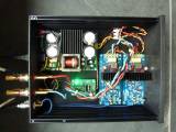
Ps. can u make a higher resolution photo of the inside.?
Wow it looks awsome! I wanna bould one exactly like yours. I have looked around the net, but cant find the chassis - will you link to it?
I am also a little bit confused about witch powersupply u use - and why so large 800? Is it this one; Connexelectronic
What is the price in total?
Thanks in advance
Ps. can u make a higher resolution photo of the inside.?
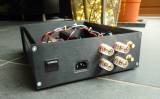
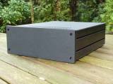
With so much discussion going on on this forum, many of you must have finished the amp by now. Please post more pictures of your finished amp, I'll post some of mine to start with.
Amp modules: L20d
SMPS: Connexelectronic SMPS800R (2 x 60V dc)
Speaker Protection: Connexelectronic, powered by Aux 12Vdc of the SMPS
Chassis: Galaxy 230x280/80 with 10mm front (and alu covers)
Maarten

Hi!
I have two questions about The IRAUDAMP7.
1) The IRAUDAMP7 data sheet (http://www.irf.com/technical-info/refdesigns/iraudamp7d.pdf) mentions various AMP7D implementations, including one AMP7D-55 running on 25V. Is this just a matter of supplied voltage (i.e. can one run any of the AMP7D kits available on for instance 30V) or does this require a specific implementation?
2) What is the input impedance of the AMP7D? In the data sheet there is this phrase in the Input Signal and Gain Setting section that says "A proper input signal is an analog signal ranging from 20Hz to 20kHz with up to 3 VRMS amplitude with a source impedance of no more than 600 Ω.". This seems to imply a quite low input impedance (probably not more than 6K ...), does anybody know for sure?
Best!
Johan
Of course higher rating is not a problem.
My question is about replacement of the kit 100V capacitors by better caps, 25V rated
I'd like to use panasonic FC caps.
If IR is suggesting 25V caps in their design, then you should be fine. It would be nice if you could build them with the supplied caps, get used to the sound and then make the cap changes, so you can see if you can identify an improvement.. (or even do one channel first and do some mono testing..) and report back to us.. ;=
There's no problem running any of the higher power implementations at lower supply voltages and thus lower maximum output power, unless the undervoltage points have been set above this supply voltage. Sorry, but I haven't checked whether that is the case.1) The IRAUDAMP7 data sheet (http://www.irf.com/technical-info/refdesigns/iraudamp7d.pdf) mentions various AMP7D implementations, including one AMP7D-55 running on 25V. Is this just a matter of supplied voltage (i.e. can one run any of the AMP7D kits available on for instance 30V) or does this require a specific implementation?
Looks like it's 3.3K, which is pretty low. It's R2 + R7. This gives a high-pass DC block at 2.2 Hz with the 22uF CP1.2) What is the input impedance of the AMP7D?
It looks like Z101 sets the minimum supply voltage (UVP), so you would need a lower voltage Zener to operate one of the higher power options at 30; 18V would be a good choice, but anything under 24V would probably do.There's no problem running any of the higher power implementations at lower supply voltages and thus lower maximum output power, unless the undervoltage points have been set above this supply voltage. Sorry, but I haven't checked whether that is the case.1) The IRAUDAMP7 data sheet (http://www.irf.com/technical-info/refdesigns/iraudamp7d.pdf) mentions various AMP7D implementations, including one AMP7D-55 running on 25V. Is this just a matter of supplied voltage (i.e. can one run any of the AMP7D kits available on for instance 30V) or does this require a specific implementation?
There's no problem running any of the higher power implementations at lower supply voltages and thus lower maximum output power, unless the undervoltage points have been set above this supply voltage. Sorry, but I haven't checked whether that is the case.Looks like it's 3.3K, which is pretty low. It's R2 + R7. This gives a high-pass DC block at 2.2 Hz with the 22uF CP1.
It looks like Z101 sets the minimum supply voltage (UVP), so you would need a lower voltage Zener to operate one of the higher power options at 30; 18V would be a good choice, but anything under 24V would probably do.
Thanks a lot cwier60, great answers! Now I understand this probably isn't an amp for me at the moment. Johan
It looks like Z101 sets the minimum supply voltage (UVP), so you would need a lower voltage Zener to operate one of the higher power options at 30; 18V would be a good choice, but anything under 24V would probably do.
ljm_ljm's L15D, L20D and L25D do not have the OVP/UVP circuitry in them (I already looked for it..), so you won't find Z101, etc from that circuit. It is a simpler design in that way.
The resistor changes that need to be made to adjust the design for various power supply voltages(and power outputs) are listed on page 37 here. Unfortunately, ljm_ljm hasn't provided a schematic, or part IDs for the design, so it would have to be reverse engineered to identify which parts need to be replaced. (something I may get to one of these days)
yes that's missing. I started the job. Did not yet identify them all.Unfortunately, ljm_ljm hasn't provided a schematic, or part IDs for the design, so it would have to be reverse engineered to identify which parts need to be replaced. (something I may get to one of these days)
The parts ref are those from the IRAUDAMP7S reference design, page 30. It's a L25D board picture.
An externally hosted image should be here but it was not working when we last tested it.
it's a preview of work in progress and there might be errors at this stage. I just found one
A question at this stage :
The reference design BOM recomends ultra-fast switching diodes for D3, D5, D6.
The kit comes with 1N4007 which are not known to be ultra-fast.
Is this something to worry about ?
Last edited:
The IRAUDAMP7D BOM shows 1N4003 for D5-6 but MUR120 for D3. D5-6 are on the output, which should be limited to the audio band. If you plan to drive this at full power at 20 kHz, then the UF diodes may be necessary, but you're probably OK with the standard diodes.The reference design BOM recomends ultra-fast switching diodes for D3, D5, D6.
The kit comes with 1N4007 which are not known to be ultra-fast.
Is this something to worry about ?
Unfortunately, ljm_ljm hasn't provided a schematic...
I thought it was followed the IR reference design, or maybe you mean the translation from schematic to board layout.
I thought it was followed the IR reference design, or maybe you mean the translation from schematic to board layout.
No, what I meant was that the IR reference design includes circuitry(OVP/UVP) that ljm_ljm left out of his design. Also, the board layout for the L15D (showing all the values) that are provided by the ebay resellers does not match the layout of the boards I purchased. The L20D layout is slightly different also, (various versions I suspect), so a reverse engineering of the boards may be required to get a true schematic.
Alkasar is doing the work of identifying the correct components for the L25D, which will help some of us, but it looks like the layout between the various boards is different enough that it may have to be done for all of them..
D
Deleted member 148505
For me, I easily identified what are to be replaced because those are unique values for resistors in the board...
Here are the values, same as page 37 of iraudamp7s datasheet
Here are the values, same as page 37 of iraudamp7s datasheet
+ -52V 4ohms。
I suggest you to change only 8 resistance.
130K 1/4W - 120K 1/4W
5K1 1W - 3K3 1W (2PCS)
2K2 1W - 1K 1W
20K 1/4W - 15K 1/4W
5K1 1/4W - 7K5 1/4W
8K2 1/4W - 9K1 1/4W
75K 1/4W - 47K 1/4W
Do not need to change the IRFI4020.
I am done with the reverse engineering to cross-reference L25 board.
For memory, the original IRAUDAMP7S is here, page 30
http://www.inductor.com/irf/iraudamp7s.pdf
L25D cross reference
The design follows almost exactly IRF reference design.
some comments:
- The components values on the board follow the reference design, except for those to adjust according to power (in red in the schematic)
R7, R8, R17, R18, R12, R114, R115, R117, CP7, CP8
- pot P1 is not there. Instead, R11 is adjusted to 300R (resistor already sold on board)
- The protection led signal is not implemented (R14, CSD1, FET2, R3, D1)
- There is an additional 15V Zener, not on the schematic. Z? on board, already soldered. It is between pins 13 and 15 of IS2092
For memory, the original IRAUDAMP7S is here, page 30
http://www.inductor.com/irf/iraudamp7s.pdf
L25D cross reference
An externally hosted image should be here but it was not working when we last tested it.
The design follows almost exactly IRF reference design.
some comments:
- The components values on the board follow the reference design, except for those to adjust according to power (in red in the schematic)
R7, R8, R17, R18, R12, R114, R115, R117, CP7, CP8
- pot P1 is not there. Instead, R11 is adjusted to 300R (resistor already sold on board)
- The protection led signal is not implemented (R14, CSD1, FET2, R3, D1)
- There is an additional 15V Zener, not on the schematic. Z? on board, already soldered. It is between pins 13 and 15 of IS2092
Hi,The IRAUDAMP7D BOM shows 1N4003 for D5-6 but MUR120 for D3. D5-6 are on the output, which should be limited to the audio band. If you plan to drive this at full power at 20 kHz, then the UF diodes may be necessary, but you're probably OK with the standard diodes.
We dont read the same bom
I read page 33 of IRF ref design. D3, D5, D6 are supposed to be mur120.D5 and D6 are indeed clamping diodes at the output. A safety protection mecansim against overvoltage at the output. The zobel R30, C13 should limit bandwith to 150kHz. This is to filter out the modulator freq. Chances are if there is an overvoltage it could go up to high freq.
I agree, there is little risk.
Not shure what D3 is for....
edit: oops, I looked too fast to the kit ! The diodes in the kit are actually UF4004, not 1N4004. So ultra fast
Last edited:
- Home
- Amplifiers
- Class D
- My design L20D IRS2092+IRFI4020H 200W8R