Ljm I recently bought 2 of the l20d modules from zoe tsang on ebay. I was told my power supply should be ok. It is 800Va maybe 1000Va (not sure on va rating as its not stated, all im going on is the voltage and the 10A fuse on each output) toroid 240V input 54V-0V-54V output, bridge rectifier and 15000 uF 83V cap on each rail.
The rails at idle measures at +/- 86.4V DC
One of the modules the 4020 chip exploded, irs2092 explode and the three closely grouped resistors in the triangle shape near the led caught fire. I have returned it + sent photos. Just waiting on the postage to reach zoe now I think. The speaker i was using was a tannoy system 800 monitor 92db/w 6Ohm impendance. Was run loud for about 5-10mins with about 0.3V signal input max likely less.
Any Ideas what could have gone wrong?
Anyway I have been testing the second module and It has run well for a couple of hours. Installed a fan just as a precaution as a fair bit of heat is coming from the inductor and I think some of the resistors.
I have seen the rail voltage drop down to about 83V at full gain
The eventual plan is to run 2 boards per power supply as I have 2 identical power supplys. 4 channels in total. Preamps and speaker protection on each channel")
The rails at idle measures at +/- 86.4V DC
One of the modules the 4020 chip exploded, irs2092 explode and the three closely grouped resistors in the triangle shape near the led caught fire. I have returned it + sent photos. Just waiting on the postage to reach zoe now I think. The speaker i was using was a tannoy system 800 monitor 92db/w 6Ohm impendance. Was run loud for about 5-10mins with about 0.3V signal input max likely less.
Any Ideas what could have gone wrong?
Anyway I have been testing the second module and It has run well for a couple of hours. Installed a fan just as a precaution as a fair bit of heat is coming from the inductor and I think some of the resistors.
I have seen the rail voltage drop down to about 83V at full gain
The eventual plan is to run 2 boards per power supply as I have 2 identical power supplys. 4 channels in total. Preamps and speaker protection on each channel
The lack of heatsinc paste was the first thing i noticed  luckily I had some so applied it before testing. It was warm when it broke but not too warm to hold.
Like I said, I was using a very small input signal so the amp cant have been outputting anywhere close to the specced output.
I really don't know what went wrong, Im thinking maybe manufacturing defect in the ic or something as the other board is fine.
luckily I had some so applied it before testing. It was warm when it broke but not too warm to hold. Like I said, I was using a very small input signal so the amp cant have been outputting anywhere close to the specced output.
I really don't know what went wrong, Im thinking maybe manufacturing defect in the ic or something as the other board is fine.
Ljm I recently bought 2 of the l20d modules from zoe tsang on ebay. I was told my power supply should be ok. It is 800Va maybe 1000Va (not sure on va rating as its not stated, all im going on is the voltage and the 10A fuse on each output) toroid 240V input 54V-0V-54V output, bridge rectifier and 15000 uF 83V cap on each rail.
The rails at idle measures at +/- 86.4V DC
One of the modules the 4020 chip exploded, irs2092 explode and the three closely grouped resistors in the triangle shape near the led caught fire. I have returned it + sent photos. Just waiting on the postage to reach zoe now I think. The speaker i was using was a tannoy system 800 monitor 92db/w 6Ohm impendance. Was run loud for about 5-10mins with about 0.3V signal input max likely less.
Any Ideas what could have gone wrong?
Anyway I have been testing the second module and It has run well for a couple of hours. Installed a fan just as a precaution as a fair bit of heat is coming from the inductor and I think some of the resistors.
I have seen the rail voltage drop down to about 83V at full gain
The eventual plan is to run 2 boards per power supply as I have 2 identical power supplys. 4 channels in total. Preamps and speaker protection on each channel
I do not recommend the use of more than +-80V DC power supply.
Because L20D above filter capacitor voltage is only 80V.
Also the voltage is too high above the power 1W 5K1 resistor reached 1.2W, this is not safe.
I recommend using +-60V to + - 70V between.
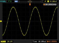
At + - 65V voltage, the output sine wave + -60 or so signal power of about 8 ohms 220W 20KHZ
Sorry, I have not tried more than DC +-80V
Attachments
Last edited:
If you must use more than +-80V power supply.
I suggest that the increase 1W5K1 resistance 1W 6K2. 1W 2K2 for the 1W 3K.
Filter capacitor for the 80V150UF to 100V 2200UF
Thanks
I'm on a tight budget and this was the closest module/amp I could find to the rail voltage I have.
When I make more progress I will start a thread on this project or something
ljm_ljm,
I was just looking at your Chinese language forum, and there is discussion there about piracy of your boards and design. Are the Ebay boards (from Hong Kong) pirated? Is there any way we can buy boards so that you get the benefit? All I could find were Taobao stores, which are hard to arrange payment and shipping for somebody who is not in China.
Also, on 1 July 2011 you posted the following comment on your Chinese language board "This is not the maximum power. Goal is to IRAUDAMP9 1200-1700W power." Have you had any further thoughts about a super big amplifier?
Thanks for all you have done for the DIY community.
.
How can we be sure that the board we purchase is not pirated and is to spec of the original design? Does ljm_ljm sell them officially somewhere? If there are differing designs where are the differences described in detail?
How can we be sure that the board we purchase is not pirated and is to spec of the original design?
The International Rectifier (IR) Reference Design can be downloaded from the Internet by googling for iraudamp7s.pdf This is your guide to make sure that what you want is what you get.
The IR RD is the basic design which ljm_ljm followed, his contribution is packaging and an excellent PCB layout leading to a low-cost, stable and easily reproducible product. When my boards arrived from Hong Kong I noted that the components had been skimped to keep the cost down. Notably the power supply bypass caps, which were only 63V types. So I soldered in some low ESR 100V replacements. Otherwise I was happy enough with the boards. They come with a logo of LJM on them, and say "designed by LJM." But there is also a twin-board floating around based off the IR design, which says it designed by IR (not LJM).
There are not many companies making the power inductor, the one ljm_ljm used is made by ICE (I think) and is used on the Hong Kong boards. The output cap seems OK. This are the first two things to check. As far as I know, the IR chips and transistors are not available from second-rate sources yet, and they should be OK. I would count none of the other components as being particularly critical, although silicone heatsink grease on the IRFI4020 is something you might inspect.
.
If you must use more than +-80V power supply.
I suggest that the increase 1W5K1 resistance 1W 6K2. 1W 2K2 for the 1W 3K.
Filter capacitor for the 80V150UF to 100V 2200UF
Thanks for this information. The 2k2 1W has definitely changed colour on my working board.
I am struggling to find these values though.
1W 6K2 - Would 1W 5K6 be suitable?
1W 3K - Would 1W 3K3 be suitable?
my board does not have 80V 150UF it has 63V 100UF.
was 2200UF a type error? Did you mean 220UF? 100v
Hello,
I would like to use L20D board for a 4ohms subwoofer. This sub is controlled by a servo and will really use close to 300W at the lower frequencies.
To achieve 300W in 4ohms, +-52V rail powersupply should be sufficient.
as trevmar mentioned, the iraudamp7s reference design pdf, fig5, shows reasonnable THD measures up to 300W with +-50V supply. This is with 4019H. 4020H should behave even better.
ljm confirmed 4020H is limited to about 9A continuus, leading to 9²*4=324W max in 4 ohms. Looks good
L20D board specs is 60 to 80V. Will it work well with +-52V ?
How can we be sure that the board we purchase is not pirated and is to spec of the original design? Does ljm_ljm sell them officially somewhere? If there are differing designs where are the differences described in detail?
L20D I have more strict production material requirements.
Including military level of materials of the PCB, plating.
Low temperature wave metal resistance, and use of Japanese make capacitors.
No matter what the time these are not change.
Thanks for this information. The 2k2 1W has definitely changed colour on my working board.
I am struggling to find these values though.
1W 6K2 - Would 1W 5K6 be suitable?
1W 3K - Would 1W 3K3 be suitable?
my board does not have 80V 150UF it has 63V 100UF.
was 2200UF a type error? Did you mean 220UF? 100v
YES。
Increase 1 W to 1 W6K2 5 K1, 5 K6 can also.
Increase 1 W to 1 W 3 2 K2 erp
Electrolytic use 100 V 100 UF-220 UF. In the radiator to the right of the two.
Hello,
I would like to use L20D board for a 4ohms subwoofer. This sub is controlled by a servo and will really use close to 300W at the lower frequencies.
To achieve 300W in 4ohms, +-52V rail powersupply should be sufficient.
as trevmar mentioned, the iraudamp7s reference design pdf, fig5, shows reasonnable THD measures up to 300W with +-50V supply. This is with 4019H. 4020H should behave even better.
ljm confirmed 4020H is limited to about 9A continuus, leading to 9²*4=324W max in 4 ohms. Looks good
L20D board specs is 60 to 80V. Will it work well with +-52V ?
+ -52V 4ohms。
I suggest you to change only 8 resistance.
130K 1/4W - 120K 1/4W
5K1 1W - 3K3 1W (2PCS)
2K2 1W - 1K 1W
20K 1/4W - 15K 1/4W
5K1 1/4W - 7K5 1/4W
8K2 1/4W - 9K1 1/4W
75K 1/4W - 47K 1/4W
Do not need to change the IRFI4020.
Or, you can consider to use L15D, L15DX2.
They are IRAUDAMP7S -150
Use the +-50 V, 250 W * 2, 4 OHM
Last edited:
L20D I have more strict production material requirements.
Including military level of materials of the PCB, plating.
Low temperature wave metal resistance, and use of Japanese make capacitors.
No matter what the time these are not change.
Where do you sell your pcb modules?
22 mfd electrolytic. Probably not the best choice.Is a cap used to decouple DC at the input
About 3.4k. You can get all the answers you need from:What's the input impedance of L20D? Need this to determine blocking cap value.
http://www.irf.com/technical-info/refdesigns/iraudamp7s.pdf
and
http://www.irf.com/technical-info/appnotes/an-1138.pdf
You may not need input blocking, depending on your application . . . if your pre-amp/crossover has either AC coupled output or servo control of its output offset. Much depends on how you're actually using the L20D . . .
Where do you sell your pcb modules?
In EABY there should be sold in China, there are some dealers in doing international trade.
If has the question to the original confirmation. Can send photos to me
ljm_ljm@foxmail.com.
I found no L20D have temporarily of piracy.
- Home
- Amplifiers
- Class D
- My design L20D IRS2092+IRFI4020H 200W8R