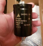
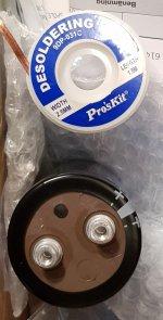
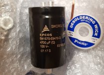
I've got 6pcs Epcos 4700uF/100V and 4pcs 10uH/12A (shielded) should I go for the transformer over the SMPS, it depends on if the toroidal transformer and the caps fit the case I have intended for this build. I think it would make a decent C-L-C-L-C filter for the L20D modules.
Those caps are some big b*stards.
Those caps are some big b*stards.
Attachments
Hello,
I have four L25D modules leftover from a project years ago and which I would like to put into use. Originally destined for 4x drivers, 8 ohm each, but now I would like to use them for 2x subwoofers, 4 ohm each.
The question: Can I parallel two modules for one driver without issue and most important, safely? I don't remember the power supply voltage I have, but it was around 60-70 V, a big SMPS module.
Would there be a need for output series resistor as is usual in paralleled amplifiers? May the output inductor already provide adequate series resistance?
I think that would be overkill, and each amp could still cause some bus pumping on its PSU.
Phase inversion on one channel in a stereo configuration is recommended in the IRAUDAMP7 Reference Design, and is actually included in that design for a single stereo half-bridge / mono full bridge switchable board. That's why I included phase inverters in my design, and also slightly increased the bus capacitors. Bus pumping is described on P26 of the IRAUDAMP7 Reference Design, and the inverter schematic is shown on P27 and P32.
Having said all that, I don't actually know how big a problem bus pumping is at normal listening volumes - it would certainly be worse in a subwoofer application, as it is happens at low frequency, high output. Someone else might have a view on this.
Perhaps you could try it first without a phase inverter, but measure the + and - voltages across the the PSU at all listening levels and for a reasonable time period (I use cheap 100W 8 ohm resistors from Aliexpress instead of speakers for testing, to save my ears and keep peace with the family and the neighbours!), and if either bus voltage starts to rise then you could add a phase inverter to one channel later.
By the way, two other modifications I made were:
- to replace the resistor that controls switching frequency with a multi-turn trimpot so I could adjust the switching frequencies on each channel to less than 5Hz of each other, to avoid interference between channels (see reference Design P21-22), and
- to replace all the 22uF electrolytic caps with Elna Silmic II caps, as these are said to give a smoother sound.
I wanted to get the best possible sound from these amps, so I thought it was worth the extra time and trouble follow the reference design recommendations, and for these other mods. And I am blown away by the smooth and effortless sound quality, as are my somewhat critical friends who were doubtful that a home-built class-D amplifier could sound this good!
Good luck with your build.
Hi,
I'll likely do as you suggest with the small inverter board.
Rather safe than sorry as the saying goes.
I don't think I have any TL071 at home, will any single opamp do?
I simply switch the speaker wires around AFTER the spkr-protection board once the phase inverter is hooked up as per your pictures?
If I can fit the whole thing in one case, I'll use the linear supply rather than the SMPS as that usually brings a rather great improvement in SQ.
Thanks for the schematic etc for the Phase inverter

Hi,
I'll use the linear supply rather than the SMPS as that usually brings a rather great improvement in SQ.
I think you'll have to do some more research on this one !
Cheers ,
Rens
The electrons spin faster in SMPS !I think you'll have to do some more research on this one !
Cheers ,
Rens
I think you'll have to do some more research on this one !
Cheers ,
Rens
Well, SQ is a highly subjective thing, isn't it?
")
The modules arrived today.
I got to work on them as soon as I had the chance.
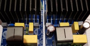
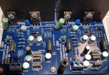
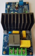
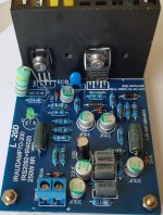
I swapped some resistors for same value but higher power rating, I removed the 150uF/80V to put in 270uF/80V of the same kind, and finally I added some overclocking grade TIM between the transistors and the heatsinks. I have to say, I think whom ever put the boards together should have at least cleaned of the flux residue.
I got to work on them as soon as I had the chance.
I swapped some resistors for same value but higher power rating, I removed the 150uF/80V to put in 270uF/80V of the same kind, and finally I added some overclocking grade TIM between the transistors and the heatsinks. I have to say, I think whom ever put the boards together should have at least cleaned of the flux residue.
Attachments
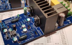
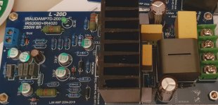
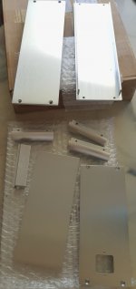
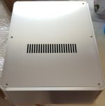
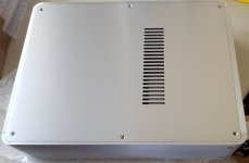
Got the enclosure today.
No idea if I'll be able to fit the linear supply in there.
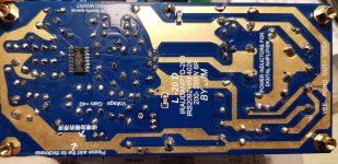
I also took pics in better light of the amp modules as they are now.
No idea if I'll be able to fit the linear supply in there.
I also took pics in better light of the amp modules as they are now.
Attachments
The modules arrived today.
I got to work on them as soon as I had the chance.
I swapped some resistors for same value but higher power rating, I removed the 150uF/80V to put in 270uF/80V of the same kind, and finally I added some overclocking grade TIM between the transistors and the heatsinks. I have to say, I think whom ever put the boards together should have at least cleaned of the flux residue.
I usually buy the kits and solder them myself - I think I can make a better job of it than the factories! And the only board I did buy pre-built had some dry solder joints that cracked and caused all sorts of problems.
I usually buy the kits and solder them myself - I think I can make a better job of it than the factories! And the only board I did buy pre-built had some dry solder joints that cracked and caused all sorts of problems.
It's a good idea to reflow all solderjoints then.
It does look like a very sloppy job tbh.
In my experience the solder used is often very bad as well.
The lack of thermal interface material was a bit of a jaw-dropper for me.
With years of experience with building PC's and custom water cooling (and overclocking of course), I know the importance of not only using thermal interface material, but using a good one.
In a CPU there are several degrees Celsius difference between a cheap, noname TIM and a really good one.
Hi,
I'll likely do as you suggest with the small inverter board.
Rather safe than sorry as the saying goes.
I don't think I have any TL071 at home, will any single opamp do?
I simply switch the speaker wires around AFTER the spkr-protection board once the phase inverter is hooked up as per your pictures?
If I can fit the whole thing in one case, I'll use the linear supply rather than the SMPS as that usually brings a rather great improvement in SQ.
Thanks for the schematic etc for the Phase inverter
DoctorData had a better layout for the inverters here (thanks Rens!), if you can make your own PCBs - I can't so I used prototype board. Keep the leads and tracks as short as possible.
I guess you could use a different op-amp, but I believe the TL071 was chosen for low noise, good for audio applications, cheap and readily available. You don't want to compromise sound on the inverted channels - I can't hear any difference between inverted and non-inverted channels using TL071.
I just reversed the speaker cable connections to the binding posts on the back of the amp (i.e spkr +ve to black post, and spkr -ve to red post) which was the easiest way for me. Just make sure the binding posts or speaker terminals are insulated from the chassis (and each other!)
Not sure if linear PS improves SQ in class-D applications - I'm sure there could be a great debate on that! I'm very happy with SQ using SMPS, they're cheap and reliable, and buying transformers here in New Zealand is a really expensive option.
Cheers, Jon.
Got the enclosure today.
No idea if I'll be able to fit the linear supply in there.
I also took pics in better light of the amp modules as they are now.
Nice looking enclosure! Looking forward to pics of the finished product.
It's a good idea to reflow all solderjoints then.
It does look like a very sloppy job tbh.
In my experience the solder used is often very bad as well.
The lack of thermal interface material was a bit of a jaw-dropper for me.
With years of experience with building PC's and custom water cooling (and overclocking of course), I know the importance of not only using thermal interface material, but using a good one.
In a CPU there are several degrees Celsius difference between a cheap, noname TIM and a really good one.
Just make sure if you're using a conductive TIM that you don't inadvertently make any shorts (not usually as problem with CPUs). But these amps don't generate that much heat anyway, even driven hard - most of the heat comes from the dropping resistors!
I only have OPA627, LT1028, OPA827, AD797 etc stocked, but I'll get some TL071's today hopefully. I do have the capability to make my own boards, thanks for the link! EDIT: I'd need to make my own board as I intend to use some 1206 size resistors and capacitors I have.DoctorData had a better layout for the inverters here (thanks Rens!), if you can make your own PCBs - I can't so I used prototype board. Keep the leads and tracks as short as possible.
I guess you could use a different op-amp, but I believe the TL071 was chosen for low noise, good for audio applications, cheap and readily available. You don't want to compromise sound on the inverted channels - I can't hear any difference between inverted and non-inverted channels using TL071.
I just reversed the speaker cable connections to the binding posts on the back of the amp (i.e spkr +ve to black post, and spkr -ve to red post) which was the easiest way for me. Just make sure the binding posts or speaker terminals are insulated from the chassis (and each other!)
Not sure if linear PS improves SQ in class-D applications - I'm sure there could be a great debate on that! I'm very happy with SQ using SMPS, they're cheap and reliable, and buying transformers here in New Zealand is a really expensive option.
Cheers, Jon.
So, you swapped the cables after the spkr-protection circuit, I.E Red to black terminal, Black to Red terminal to keep it simple. Of course I'll keep all terminals and jacks isolated from the chassis, but I understand why you say not to forget it. I keep RCA jacks isolated from each other as well.
I like to star-ground my builds, I guess there's no issue doing that in this case?
Thanks! I thought so as well. I'll try to get some pics along the way using my DSLR.Nice looking enclosure! Looking forward to pics of the finished product.
Tbh, non-conductive/conductive TIM is as much a concern in PC overclocking as in DIY audio. I don't just water cool and overclock CPU, but also GPU. I wouldn't use anything like liquid metal between the transistors and heatsink.Just make sure if you're using a conductive TIM that you don't inadvertently make any shorts (not usually as problem with CPUs). But these amps don't generate that much heat anyway, even driven hard - most of the heat comes from the dropping resistors!
Dropping resistors, I'm guessing these are the ones I've swapped? 2K2 is now 5W and 5K1 is 3W. That should be ok, if not there's a serious design-flaw as this is Class D, supposedly very efficient, and not Class A.
I got some 10uH/12A rated shielded inductors to use, if I manage to fit the toroidal transformer and the lytics, in a C-L-C-L-C filter. However, they look so small lol
I may just wind my own aircore inductors for the filter.
Last edited:
So, you swapped the cables after the spkr-protection circuit, I.E Red to black terminal, Black to Red terminal to keep it simple.
I like to star-ground my builds, I guess there's no issue doing that in this case?
Yes, just swapped the speaker cables as you said.
Shouldn't be any issue with star-grounding, but I had a problem with hum, only when connected to my Onkyo AV receiver (as DSP and pre-amp) and couldn't find any way of stopping this other than either disconnecting chassis earth (dangerous - not advisable) or to disconnect the SMPS ground plane from the chassis (by cutting the PCB trace by the screwhole that grounds it), so the SMPS, L15Ds, speaker protection circuits, binding posts and RCAs are all on a virtual ground (i.e. not connected to the chassis, which is still earthed.
Mind you, this is in a 7-channel system with two SMPS, so lots more opportunities for ground loops! May be fine in a 2-channel system with a linear supply.
Dropping resistors, I'm guessing these are the ones I've swapped? 2K2 is now 5W and 5K1 is 3W. That should be ok, if not there's a serious design-flaw as this is Class D, supposedly very efficient, and not Class A.
I mean the two 3.3K 1W resistors (R117 and R118 in the reference design) - those resistors, as supplied, can get up to 80 degrees celsius! But that's still within their tolerance so I didn't bother swapping them - I have a 120mm 12V fan exhausting heat from the enclosure, running off the SMPS 12V rail but undervolted to around 6V for low noise, and there's very little heat coming out from what is quite a cramped layout, no matter how hard I drive it. heatsinks only get warm and there's negligible heat from any of the other resistors or the inductors.
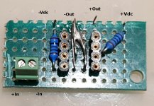
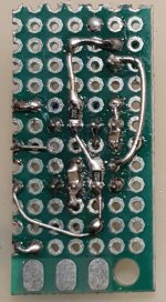
I figured it would be better to try the phase inverter before going through the hassle of etching a board. So I put together quick version of it to test.
I need to clean it up and touch up a few solder joints, but it measure ok on the DMM.
I need to clean it up and touch up a few solder joints, but it measure ok on the DMM.
Attachments
Because now the Philippines production IRFB4020 has serious quality problem.
So I recommend using the IRFI4020H L20D.
And is not recommended to use L25D IRFB4020
I did not see this before I order my L25D kits. When I receive it last month, IRFB4020 just not working, but after notified my seller, he send 2 more for me. However, when I finish the amp it work for about 20 minute then it die and there are -60 volt at output. How should I fix this.
- Home
- Amplifiers
- Class D
- My design L20D IRS2092+IRFI4020H 200W8R