I purchased an L30D board off of Ebay and it arrived DOA. LED doesn't light up & I'm reading 2.9vDC on the speaker output. The seller asked me to send it back to him but That will be expensive so I'd like to try to fix it.
There's no visible damage to the board or any components. I'm okay with a soldering iron but I have no scope. Hopefully it's not a dead IRS2092 because I'm not very good with soldering SM... Any ideas of what I should check 1st?
Thanks
There's no visible damage to the board or any components. I'm okay with a soldering iron but I have no scope. Hopefully it's not a dead IRS2092 because I'm not very good with soldering SM... Any ideas of what I should check 1st?
Thanks
Last edited:
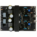
Sure electronic board 250w IRS2092 IRFI4020H
Hi Grib,
My speaker system is 8ohms and it says it can can drive up to 300w peak power.
left channel of the amp starts shutting down for base punch when i increase the volume level. it keeps shutting down when i increase volume level more. when i lower the volume level, it starts to work again. however the right channel works properly.
Ok, pretty sure it's the over current limit.
One of the resistors for adjusting OC is probably out of tolerance on the left channel.
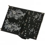
Can you provide the board reference, and a picture of both sides of the board please
Ok, pretty sure it's the over current limit.
One of the resistors for adjusting OC is probably out of tolerance on the left channel.
Can you provide the board reference, and a picture of both sides of the board please
Hi Grib,
This is a sure electronic board. But it is carbon copy of IRAUDAMP7S-200 reference design of International Rectifier. I have attached here with some docs.
Attachments


Apparently, this board implements the under voltage protection, so measure your left PSU voltage when the board shuts down to see if it doesn't drop bellow the minimum allowed.
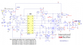
If the voltage is correct, it's probably the OC limitation. You'll just have to read the IRS2092 application note, and try different couples for R18/R19 and R12/13 to increase the threshold.
http://www.infineon.com/dgdl/an-1138.pdf?fileId=5546d462533600a40153559a077610d1
If the voltage is correct, it's probably the OC limitation. You'll just have to read the IRS2092 application note, and try different couples for R18/R19 and R12/13 to increase the threshold.
http://www.infineon.com/dgdl/an-1138.pdf?fileId=5546d462533600a40153559a077610d1
Apparently, this board implements the under voltage protection, so measure your left PSU voltage when the board shuts down to see if it doesn't drop bellow the minimum allowed.
If the voltage is correct, it's probably the OC limitation. You'll just have to read the IRS2092 application note, and try different couples for R18/R19 and R12/13 to increase the threshold.
http://www.infineon.com/dgdl/an-1138.pdf?fileId=5546d462533600a40153559a077610d1
Hi Grib,
Thank you very much for the answer. I will check those one by one. Can you pls tell me what should i do if the the PSU voltage is dropped down below the minimum allowed?
Below are some of details of my power supply.
Transformer - ac 45-0-45/ 600w
Rectifier - Full bridge 60A
Filter caps - 2x20000uf/ 100v
I though this board needed two PSU ?
If it's powered by a single PSU it can't be the source of your problems. Both channels would shut down at the same time.
Anyways, it's unlikely that your PSU is dropping bellow 55V. 600W is decent and your caps are well sized.
It is most likely the OC tripping.
If it's powered by a single PSU it can't be the source of your problems. Both channels would shut down at the same time.
Anyways, it's unlikely that your PSU is dropping bellow 55V. 600W is decent and your caps are well sized.
It is most likely the OC tripping.
Temperature on L15D boards?
Hope someone can answer a question about temperatures on L15D boards.
I'm really enjoying my 7-channel "baking tray" power amp, which uses LJM L15D kit boards (photos in the gallery <here>)- just seems to sound smoother & warmer the more I run it. Just waiting for some Silmic caps to arrive to replace the input caps, and will also replace the buffers with Rubycon 820uF/63V at the same time, plus drill some more ventilation holes in the base, for better airflow.
Which leads me to my question. My enclosure's a bit cramped (see photos) and I'm feeling some heat coming out after a few hours running - nothing too worrying, but I thought I'd check the innards to make sure.
Ambient temperature is around 23C and the two SMPS's (+/-55V, 500W) don't even break a sweat. The L15D heatsinks get warm at around 40-50C, which seems reasonable. However, the output inductors are over 60C , and the 3.3K 1W dropping resistors (for IRS2092 VAA and VSS) are around 75-85C or higher !
So most of the heat is coming from the inductors and dropping resistors, rather than the MOSFETs - is this normal? Are these temperatures OK, or is there anything I need to do about them?
Thanks
Hope someone can answer a question about temperatures on L15D boards.
I'm really enjoying my 7-channel "baking tray" power amp, which uses LJM L15D kit boards (photos in the gallery <here>)- just seems to sound smoother & warmer the more I run it. Just waiting for some Silmic caps to arrive to replace the input caps, and will also replace the buffers with Rubycon 820uF/63V at the same time, plus drill some more ventilation holes in the base, for better airflow.
Which leads me to my question. My enclosure's a bit cramped (see photos) and I'm feeling some heat coming out after a few hours running - nothing too worrying, but I thought I'd check the innards to make sure.
Ambient temperature is around 23C and the two SMPS's (+/-55V, 500W) don't even break a sweat. The L15D heatsinks get warm at around 40-50C, which seems reasonable. However, the output inductors are over 60C
, and the 3.3K 1W dropping resistors (for IRS2092 VAA and VSS) are around 75-85C or higher ! So most of the heat is coming from the inductors and dropping resistors, rather than the MOSFETs - is this normal? Are these temperatures OK, or is there anything I need to do about them?
Thanks
Hope someone can answer a question about temperatures on L15D boards.
I'm really enjoying my 7-channel "baking tray" power amp, which uses LJM L15D kit boards (photos in the gallery <here>)- just seems to sound smoother & warmer the more I run it. Just waiting for some Silmic caps to arrive to replace the input caps, and will also replace the buffers with Rubycon 820uF/63V at the same time, plus drill some more ventilation holes in the base, for better airflow.
Which leads me to my question. My enclosure's a bit cramped (see photos) and I'm feeling some heat coming out after a few hours running - nothing too worrying, but I thought I'd check the innards to make sure.
Ambient temperature is around 23C and the two SMPS's (+/-55V, 500W) don't even break a sweat. The L15D heatsinks get warm at around 40-50C, which seems reasonable. However, the output inductors are over 60C
So most of the heat is coming from the inductors and dropping resistors, rather than the MOSFETs - is this normal? Are these temperatures OK, or is there anything I need to do about them?
Thanks
Dont worry , after about 4 years , mine are still working OK and room temperatures here are mostly about 28 to 30 celcius during daytime in summer .I changed the output inductors to original Sagami's and they run about 10 degrees cooler and have much lower resistance (http://au.rs-online.com/web/p/leaded-inductors/7511847/) . Make sure your fan is sucking out the hot air and not blowing in to the enclosure and have holes drilled in your bottom baking tray under the L15D heatsinks . This will increase airflow and cool down your case and components .The power resistors have no problem with 85 degrees , there is some power derating , but all within specs .
Cheers ,
Rens
Last edited:
Sure electronic board 250w IRS2092 IRFI4020H
Hi Grib,
I replaced R12/13 and R18/19. It seems like the amp work good now. Thanks for helping me to Fix the issue.
I need you to get some advice for below my query.
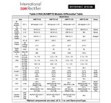
My amp is a carbon copy of of reference design of IRAUDAMP7S-200 - International rectifier.
I need to run the my amp with 4ohms load. But the amp is not stable at higher volume level. Reason could be the over current protection. According to the data sheet, IRAUDAMP7S-200 is recommended only for 8ohms.
However the Model IRAUDAMP7S-150, this amp can be run at 4ohm load, But power MOSFET are difference in this model.
Do you thing it is a good idea to change the current sensing resistors (R12, R17, R18) of my amp (IRAUDAMP7S-200) as the IRAUDAMP7S-150 so that i can run my amp with 4ohm load? will it be create any harm to the component of the board?
I though this board needed two PSU ?
If it's powered by a single PSU it can't be the source of your problems. Both channels would shut down at the same time.
Anyways, it's unlikely that your PSU is dropping bellow 55V. 600W is decent and your caps are well sized.
It is most likely the OC tripping.
Hi Grib,
I replaced R12/13 and R18/19. It seems like the amp work good now. Thanks for helping me to Fix the issue.
I need you to get some advice for below my query.
My amp is a carbon copy of of reference design of IRAUDAMP7S-200 - International rectifier.
I need to run the my amp with 4ohms load. But the amp is not stable at higher volume level. Reason could be the over current protection. According to the data sheet, IRAUDAMP7S-200 is recommended only for 8ohms.
However the Model IRAUDAMP7S-150, this amp can be run at 4ohm load, But power MOSFET are difference in this model.
Do you thing it is a good idea to change the current sensing resistors (R12, R17, R18) of my amp (IRAUDAMP7S-200) as the IRAUDAMP7S-150 so that i can run my amp with 4ohm load? will it be create any harm to the component of the board?
Attachments
As long as you keep a working OC protection, and that you keep it bellow the maximum that the MOSFET can handle, you should be ok (36A for IRFI4020, so don't exceed 30~32A).
The main side effet of running 4 Ohms speakers would be the change is high frequency response. You will most likely get a ~3dB boost or cut (I don't remember), at 20k, with a huge Q factor, so that would affect 14k (lightly) up to 20kHz (a lot). That would have to be confirmed by some else, I'm not sure.
The main side effet of running 4 Ohms speakers would be the change is high frequency response. You will most likely get a ~3dB boost or cut (I don't remember), at 20k, with a huge Q factor, so that would affect 14k (lightly) up to 20kHz (a lot). That would have to be confirmed by some else, I'm not sure.
As long as you keep a working OC protection, and that you keep it bellow the maximum that the MOSFET can handle, you should be ok (36A for IRFI4020, so don't exceed 30~32A).
The main side effet of running 4 Ohms speakers would be the change is high frequency response. You will most likely get a ~3dB boost or cut (I don't remember), at 20k, with a huge Q factor, so that would affect 14k (lightly) up to 20kHz (a lot). That would have to be confirmed by some else, I'm not sure.
Hi Grib,
Thanks, I have another query, operating voltage also different of IRAUDAMP7S-150 and IRAUDAMP7S-200. do you thing the board will be malfunctioning if i change current sensing resistors of mine as IRAUDAMP7S-150?
I changed the output inductors to original Sagami's and they run about 10 degrees cooler and have much lower resistance (7G17B-330M | SAGAMI ELEC 33 μH 20% Leaded Inductor, 7.5A Idc, 10.7mΩ Rdc 7G17B | SAGAMI ELEC) . Make sure your fan is sucking out the hot air and not blowing in to the enclosure and have holes drilled in your bottom baking tray under the L15D heatsinks . This will increase airflow and cool down your case and components .The power resistors have no problem with 85 degrees , there is some power derating , but all within specs .
Cheers ,
Rens
Thanks Rens, hoped you'd know the answer. Fan is definitely sucking (though deliberately quite slowly, for near-silence!), but when I remove the boards to change the caps I'll drill a pattern of holes underneath for more airflow - most is coming in through the back panel at the moment. Might try changing the inductors at the same time too. But good to know there's nothing to worry about in the meantime.
Cheers,
Jon.
L15D-SMD and L15D capacitors question
Hoping that someone can answer these two questions. My 7-channel power amplifier uses 3x stereo LJM L15D kits (six boards), and one pre-assembled LJM L15D-SMD board (I couldn't find where I could buy a mono L15D, and I'm limited for space too).
The L15D boards have six 33uF/35V mini electrolytic capacitors , but the L15D-SMD has eight standard-size (Rubycon)electrolytics, and they're 100uF/35V. It also has two additional transistors, Q1 (H649A) and Q2 (D669A), which aren't on the L15D boards or the reference design. They look like they're part of the supply voltages to IRS2092, but I'm not really sure what they're for, and the extra electrolytics seem to be associated with these transistors.
I want to replace the electrolytics with Silmics. So my questions are:
1. Is it Ok to replace the 33uF/35V electrolytics on the L15D boards with 22uF/35V Silmics? (I've got 100x 22uF/35V Silmics already from another project)
2. Which caps should I replace on the L15-SMD board (e.g. all of the 100uF/35V ones? Or just six, in which case which six?), and can I replace them with 22uF/35 Silmics, or do they need to be 100uF/35V (and why?)
Any advice gratefully received. Thanks.
It makes no sense to replace those capacitors with Elma's . wast of time and money. Only CP1 22uF just right from the input connector is in the signal path and will make a difference .
I have no expierience with the smd version , maybe under voltage or some other protection ? Have a look at the reference design iraudamp7s and try to reverse engineer the PCB .
Cheers ,
Rens
Ah, yes, of course, wasn't thinking clearly. ThanksOnly CP1 22uF just right from the input connector is in the signal path and will make a difference .
")
Send you a PM .Ah, yes, of course, wasn't thinking clearly. Thanks
Cheers ,
Rens
Last edited:
Send you a PM .
Cheers ,
Rens
could not ad picture to PM , here you go !
Cheers ,
Rens
Attachments
I bought this amp on ebay.It is low price and goid sounding.I think on of the best high power digital amps.Specialy because of the excellent infinion 2092 driver ic.But it is far away from Top high end sound.The treble bring not the dynamic and clearness of some other high end amps.But better than some 2000 Euro store amps.
- Home
- Amplifiers
- Class D
- My design L20D IRS2092+IRFI4020H 200W8R