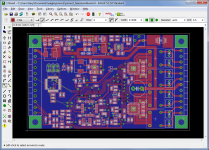
Well, didn't get it done last night... and lots of stuff going on today so I don't think it'll be done tonight, sunday perhaps. I moved around a bunch of stuff, somehow cramming the design even tighter now, to make room for configuration switches. Going to attempt to wire up a 4-way "SOIC switch".
Snapshot attached of where it sits.
Saturnus: Thanks for the info. If I manage to squeeze in 4 switches, it might become 8 configurations yet. I'll worry about that stuff later when "production board time" rolls around. It'd be nice to get some frequency sweeps of Boominator boxes, in various configurations, to set up the default EQ curves.
Edit: Pricing... for a bare PCB and parts, I'd say $75 to $100 in reasonable quantities (say, 10+). For a prebuilt PCB I have absolutely no idea at this point, I haven't spoken to any manufacturers.
Attachments
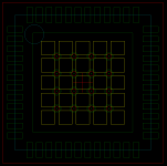
My only comment would be move the thermal vias apart a bit to allow solder between them, and to size the pads so that you can get a solder mask dam between the pins, this is critical for these devices to avoid shorts between the pads. Beware though most PCB manufacturers will cry and try and remove these solder mask dams when they front end engineer your Gerber data.
If you can find it IPC-7093 is an excellent spec covering all aspects of these type of components.
The picture shows the footprint I use for 7x7,mm QFNs' the yellow squares are where the solder paste is deposited, the thermal vias used are 0.25mm finished drill size with a 0.6mm land (IPC-class 3 compliant). This allows us to get the recommended 50-70% solder coverage of the thermal pad, and minimises the amount of solder that disappears down the vias.
Marc
Attachments
Glad to help, I've layed out loads of boards with these type of devices, they are fast becoming the only choice with some devices. They are excellent for getting the heat out of the actual chip, they fix them to the thermal pad. But from an assembly point of view they are a pain, but having an x-ray ATE system helps. With the power devices getting a good joint between the thermal pad and the board can be critical for heat dissipation. The thermal pad to case works well, even though they are expensive, also allows you to have a totaly enclosed product to IP67, very waterproof. If you have a look at engine ECUs and similar, the cases are now being moulded with heat fins as an integrill part of the enclosure, free heatsinking and easy assembly, the pads also have some give so you dont stress the board. I always add mounting hole near any devices that require the heatsinking and where the pads are, you dont want the board to bend with theses components, the lack of any legs means the solder joints can be easily stressed if the board bows.
It a nice looking design.
It a nice looking design.
A bit more info...sorry
by coincident someone asked a question about thermal design on a Electronics/PCB forum I frequent, so I thought the links I put up there will illustrate what I have said in more detail. The last link is specifically for QFN's and is a good read.
Thermal Vias – A Packaging Engineer’s Best Friend Electronics Cooling Magazine – Focused on Thermal Management, TIMs, Fans, Heat Sinks, CFD Software, LEDs/Lighting
http://www.gendreaumicrosystems.com/images/d2pak-thermal-vias.JPG
http://powerelectronics.com/mag/602PET22.pdf
http://www.ti.com/lit/an/snva183a/snva183a.pdf
http://www.cirrus.com/en/pubs/appNote/AN315REV1.pdf
Thermal data for some vias...
0.5mm finished 0.025mm Cu plating min 176 degC/W
0.7mm " " " " " 102 degC/W
Last edited:
Whew. Layout almost there. Things left to do:
- Figure out QFN/MSOP-EP thermals
- Silkscreen. The thing's so densely packed that it's going to be a headache
- Pick a cheap but suitable board house to get the PCB made
- Probably start pouring some top side planes (power/ground/etc)
- Add some ESD protection to the control inputs/status outputs
- Clean up the schematic to make it 'shareable'
I upgraded my Eagle install to 6.1, using the freeware license. Turns out that the freeware tools only let you edit the first schematic sheet, and this project has two schematic sheets. Dunno if it's a bug, but you can actually edit the 2nd sheet via cloning and copy/pasting from the first page - pain in the *** to do, but it works. Hopefully Cadsoft leaves this 'feature' in there, otherwise I gotta find a way to move everything onto the first sheet.
Attachments
You won't be able to parallel a pair of outputs to drive 30W into 2 ohms.
But, you'll be able to make pairs of outputs drive the same signal, and drive a pair of 4 ohm speakers in the same airspace, with the same end result. Unless you've got specific 2 ohm speakers you want to use, you should be OK.
But, you'll be able to make pairs of outputs drive the same signal, and drive a pair of 4 ohm speakers in the same airspace, with the same end result. Unless you've got specific 2 ohm speakers you want to use, you should be OK.
Latest update:
I'm adding a header to allow plugging in an ADI "USBi" interface, allowing realtime adjustment/tuning of speaker parameters. I might also try to sneak an I2C EEPROM into the design for the SigmaDSP to boot from, allowing retuning without reprogramming the Atmel, though space is tight for that.
Still not sure what to do about QFN heatsinking. Vendors are recommending 0.3mm holes for heatsinking, minimum drill on the board is 0.5mm which is a limitation of most "hobby sized" board houses I normally deal with. I'm even contemplating moving that up to 0.6mm so I can get Olimex to build the board and save a few bucks. I'll probably swiss-cheese under the QFN and just fill the whole mess with solder by hand, and when/if volume manufacturing of this board happens, I'll work out a 'proper' QFN footprint then.
As for volume manufacturing, I really couldn't be bothered to invest time/money in taking orders, ordering parts, finding an assembly shop, etc - I'd sooner let someone else handle all that. If I can get enough interest from people, I might even pitch the idea to Sparkfun:
Pitching Your Product - SparkFun Electronics
I think there's a few other companies around that do the same sort of thing. We'll see, I'm more concerned with getting a prototype built/working at this point.
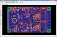
Board layout is DONE. Not quite cellphone dense, but it's close. Had to angle the board name/version/author in order to fit it on the board. The board name "BOOMINCARD" is just a placeholder, it's midnight here and I'm too tired to think of something more clever right now.
Smallest drill is 0.6mm, allowing the board to be built at Olimex. Two boards fit on a 30 euro DSS panel. Not optimal for manufacturing, but for prototyping, it's fine.
I added a 6 pin header which has the SigmaDSP reset and I2C pins. This allows the SigmaDSP code to be modified on the fly with SigmaStudio if you have a "USBi" interface. On that note I'm going to try building a USBi clone myself, but I think Analog Devices would kill me if I attempted to sell them.
Schematic... I created 2 schematic sheets in Eagle Hobby, then upgraded Eagle to version 6 which I don't have a hobby license for... and I can't get everything back onto one sheet. Once I get that figured out, and get the schematic cleaned up a bit, I'll release the design files. I'll hopefully get that straightened out in a couple of days.
Attachments
Fantastic work, gmarsh.
In regards to naming convention of the different amps I have some ideas. I have an affinity for Aston Martin db-series cars, and wanted to name amps after those as it also fits perfectly. db can be seen as both dB and an abbreviation of "the Boominator" ("da Boominator"). At the same time the 2 mainly used amp today are amp6 and amp9 from 41.hz, those fit the db6 and db9 cars. The t-amp mk2 would fit the dbV with V for value, and your would fit the dbS name with S for Signature. So in short:
dbV - t-amp 2024 mk2 - value 2 channel amp for a low cost usually half boominator
db6 - 41.hz amp6 - classic solid 2 channel amp for the classic boominator build
db9 - 41.hz amp9 - high power 4 channel amp for a semi-pro boominator build
dbS - GMarsh Signature design - DSP controlled 4 channel specially optimized amp for any boominator build but especially suited for a Signature extremely low wieght, high sound quality, and high output boominator build
I will have to test it naturally, as would you, but I don't see any reason why I shouldn't recommend this amp as the primary amp for any boominator (or other high quality boombox) builder, unless they are very short of cash. It is the perfect storm of everything anyone could ever want from an amp suited for portable use.
Aston Martin, DB = David Brown of tractor Fame
This may be of interest for prototyping, excellent for good results on QFN's:
StencilMate Evaluation Kits
This may be of interest for prototyping, excellent for good results on QFN's:
StencilMate Evaluation Kits
Neat. Ordered a sample, hopefully it ends up being for a 7mm QFN48 
I'm planning to tin the part by hand, tin the board and fill the vias under the QFN with solder, coat everything in tacky flux and use our BGA rework station (bottom heat + top hot air) to solder the part. This is only being done for two prototypes that I'm building, anything beyond that is getting built by machines.
As for card names, I'm hoping this thing ends up being more reliable than a British car. My card has 4 channels so I could call it the Quattro... or maybe I'll name the AMP9 that, and since my card "comes with the works" I could call it the WRX. *shrug*
As for card names, I'm hoping this thing ends up being more reliable than a British car.
The Aston Martin isn't a British car. It's the epitome of automotive engineering.
Being compared to a $300.000 base price car isn't too shabby
Oh, it's a British car... and in addition to British reliability, 99% of people out there can't afford it. Not liking this comparison
(Ignore me. Call the thing whatever you want.)
Update: Board isn't done. Putting together a parts order now, just realizing I goofed on the LC output filter capacitor choice. Seems 1.5nF and 1.5uF are two different things, and one of them is a lot bigger than the other... d'oh. On a positive note, it looks like PCB+parts for two cards are going to be less than $100/card. Hoping that given enough volume, I can manufacture a card for the same.
So what's this signature thing all about? I know you're using different drivers, what else is changing?
It's also using the original design for CNC router manufacturing with interlocking edges instead of the easier DIY design with straight edges. As well as using the far superior LiFeYPO4 batteries instead of SLAs.
- Total weight will be about 12kg (including batteries) compared to 25kg
- Sensitivity is 3dB higher so it can in principle play twice as loud for the same amount of watts
- Much better sound quality and improved bass performance
- Total weight will be about 12kg (including batteries) compared to 25kg
- Sensitivity is 3dB higher so it can in principle play twice as loud for the same amount of watts
- Much better sound quality and improved bass performance
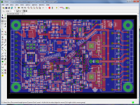
There's three:Having a more detailed glane at the PCB are there a couple of little switchers on there for different voltages?
- Top center/right: LT3652HV MPPT battery charger
- Top left: LT3680 DC/DC for +5V USB output.
- Dead center: LTC3103 DC/DC for +3.3V audio bits. Atmel AVR is run off a separate +3.3V provided by a small LDO.
I paid for an Eagle 6 upgrade last night, hopefully that'll go through today and I'll have a shareable schematic by the end of tonight.
- Status
- This old topic is closed. If you want to reopen this topic, contact a moderator using the "Report Post" button.
- Home
- Amplifiers
- Class D
- Purpose-built Boominator PCB project