From today I know that 1 NC400 + Before hearing them I thought of some comparison tests with my Marantz SM-11S1 (which is not a bad amp), but after listening to them for 5 hours now, I don't want to go back....
...they worked perfectly from the first time I have powered them up. I am using balanced cabling to my (AudioNote DAC4.1X) DAC.
Wow...Ncore successfully replaces another amp (Marantz SM-11S1) I admired and wanted since hearing it power KEF Reference stand mounts...the list of truly exceptional amps fallen to Ncore ever grows. I suppose Audiogon is happier than amp makers other than Hypex. Thanks for mentioning this. I gotta assemble my three Ncore amps.
I don't believe that's Hypex's business model at all. Apart from the nc400 & smps600 all other of hypex's products are (nearly always) available from stock, and Jan Peter has recently quoted a 2 week lead time on orders - that's not build to orderHypex' current business/marketing plan is very simple. Hypex fill confirmed, fully prepaid orders.
In the case of the nc400/smps600 I think it is simply a case of
- you always control the maximum size of initial production runs, so that you control the potential size & cost of any initial production rework problems
- they've been surprised by the level of demand
Didn't Bruno say something about he believed the 1st production batch would last til Christmas? (misremembered, but he certainly implied the demand for the 1st batch far exceeded his expectations)
Traditional puddings have their place. They're almost impossible to find in an eatery in the UK now. They seem to have been almost universally replaced by something called 'chocolate fudge cake'If it measures like a pudding it must be a pudding - and you therefore have to like it, unless you are crazy and have developed a use of your taste buds and have the strange thing called a taste.
Compression is a complex phenomenon; difficult to illustrate with numbers (even our hearing system has built in "protection" to compress sound when necessary).
At the other thread someone came up with a modern 98 dB efficient 18 inch woofer which specifies only 1.8 dB compression at its 800 watt maximum power level (seems not too easy to measure anyway IMO).
More realistic (lower efficiency; smaller) domestic systems will have higher rates of dynamic compression, and a good quality amplifier will not be the limiting factor in this regard IMO.
Interesting. Following on from Bruno's 'challenge' about transconductance amps I came across this http://www.essex.ac.uk/csee/research/audio_lab/malcolmspubdocs/J12%20Distortion%20reduction%20MC%20current%20drive.pdf
Interesting observations in there about non-linearities with displacement, change in drive unit distortion with temperature as well as change in drive unit parameters and therefore change in crossover characteristics. Time and operational dependent 'compression'. It's an old paper but I wonder how much has really changed in current moving coil loudspeakers
Thanks Chris,
Seems to be an excellent article; 1989, but IMO nothing shocking has changed in moving coil speakers since.
Thoughts on a transconductance ncore
Probably going really off-topic
(but, of course, nothing else in this thread has been off-topic") )
)
So we've got a big stable power op amp block.
And therefore I was going to say that implementing a transconductance amp was relatively straightforward,
...until I read section 4/page 144 of Distortion Reduction in Moving-CoilLoudspeaker
Systems Using Current-Drive Technology which indicates that a loop gain of > 92 dB is required - nc400 specified as > 56 dB.
However Esa Merilainen/Current Drive claims to have successfully implemented a transconductance amp using a TDA2040 Transconductance amplifier project - Current-Drive - The Natural Way of Loudspeaker Operation
Also it's not so immediately straightforward if we want a balanced input transconductance amp.
With regards the ncore itself, We need to know which components on the ncore are the input - so that effectively we know which are the +ve and -ve input terminals of the opamp - and feedback resistors
We need to know what external compensation components (if any) are also required
We also need to be sure of the block diagram/circuit diagram of the input buffer stages of the ncore.
Anyone done an analysis/schematic?
...or Bruno do it for us
Thoughts about current drive and crossovers
current drive means the amp produces the current whatever the load and whatever signal is actually being converted by the transducer (speaker drive unit)
So outside the driver's operational range, if we don't want the current to go into the driver it has to go somehwere else. So we've got to sink it in the crossover. This seems extremely inefficient. So active crossovers (DSP) is a very sensible way to go.
DLCP please?
Probably going really off-topic
(but, of course, nothing else in this thread has been off-topic
)- the ncore (and ucd) are designed as big stable audio opamps (instrumentation amps)
- and as we know they have loads of negative feedback as that's a core part of the reason why the closed loop performance at 20k is so good
- and that the audio implementation of the ncore should be considered to be (is) entirely an analogue device
- it's (unconditionally?) stable over the audio band
- it's deliberately unstable, in a (fully?) controlled way, at the self-oscillation frequency
So we've got a big stable power op amp block.
And therefore I was going to say that implementing a transconductance amp was relatively straightforward,
...until I read section 4/page 144 of Distortion Reduction in Moving-CoilLoudspeaker
Systems Using Current-Drive Technology which indicates that a loop gain of > 92 dB is required - nc400 specified as > 56 dB.
However Esa Merilainen/Current Drive claims to have successfully implemented a transconductance amp using a TDA2040 Transconductance amplifier project - Current-Drive - The Natural Way of Loudspeaker Operation
Also it's not so immediately straightforward if we want a balanced input transconductance amp.
With regards the ncore itself, We need to know which components on the ncore are the input - so that effectively we know which are the +ve and -ve input terminals of the opamp - and feedback resistors
We need to know what external compensation components (if any) are also required
We also need to be sure of the block diagram/circuit diagram of the input buffer stages of the ncore.
Anyone done an analysis/schematic?
...or Bruno do it for us
Thoughts about current drive and crossovers
current drive means the amp produces the current whatever the load and whatever signal is actually being converted by the transducer (speaker drive unit)
So outside the driver's operational range, if we don't want the current to go into the driver it has to go somehwere else. So we've got to sink it in the crossover. This seems extremely inefficient. So active crossovers (DSP) is a very sensible way to go.
DLCP please?
typical pieter: as in the other thread, failing to take or it seems even acknowledge the whole argument because its convenient for your story.
sorry guys I actually just popped in to see what the state of the order lists etc are from end users as i'm still considering trying one of these on my subs, but since my ears are burning I couldnt help the reply. pieter enters the wire thread every now and then to tell us what the Class D guys are saying and for a spot of sport, I see he uses the same stirring tactics here.....
I drew a parallel between this argument and the one against too high damping, which seems to be precisely what you are talking about here with current drive; yet 'for the sake of argument' pieter; you claimed you couldnt see the parallel.....
Last edited:
Lead time info NC600 & SMPS600
Guys,
Currently all NC400 and SMPS600 are on stock, however we have had some unforeseen delay due to missing SMPS and audio cables....
The cables are now in transit and will arrive next week on Monday.
All open orders (and new orders...) will be shipped next week, starting on Tuesday.
My appologize for this unforeseen delay.
Guys,
Currently all NC400 and SMPS600 are on stock, however we have had some unforeseen delay due to missing SMPS and audio cables....
The cables are now in transit and will arrive next week on Monday.
All open orders (and new orders...
) will be shipped next week, starting on Tuesday.My appologize for this unforeseen delay.
Thoughts about current drive and crossovers
Very interesting.
How would this loop mechanism affect available output power for a given load?
I have done a lot a tests with a simple resistor inline with my amplifier (you can simulate that with WinISD Pro). The higher the resistor compared to the load, the closer you are from pure current drive (but of course the more power you are burning into the resistor...).
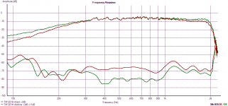
Concerning the way current drive modify the frequency response in my experience it really depends on the impedance plot of the driver. So you typically get a "boost" in the lower frequencies (when approaching resonance) and in the upper range if the driver has its impedance rising (which is no more the case with modern motors sporting shorting rings).
I found the benefits were great for a mid woofer (use above resonance) but not so for a woofer (electrical damping has its benefits) and compressions drivers (no distortion reduction).
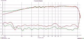
Here are two measurements with a modern midwoofer JBL 2020H, and a somewhat older design TAD TM1201H (older but better due to its great cone), measured in a ~50L closed box with and without a 44ohms resistor. The distortion shown here is 3rd order.
As you can see the JBL is more "stable" in its upper range, because its impedance does not rise as much.
The TAD also has more distortion in the low frequency that is not reduced by current drive (it is even increased, but it is only the effect of the boost: eq it and the distortion is the same), due to its small xmax.
The benefits for distortion are obvious.
sorry for the OT...
Attachments
Last edited:
the basic schematic for a transconductance 'op amp' is given in fig 23 in Distortion Reduction in Moving-Coil Loudspeaker Systems Using Current-Drive TechnologyVery interesting.
How would this loop mechanism affect available output power for a given load?
The load is in the feedback loop of the amp
The power delivery of the amp is determined by the total power going both into the load and the 'gain' resistor - Rf, the resistor to ground
The ability for the amp to correct for errors in the delivered current is dependent upon its output impedance multiplied (divided) by the fact that it's contained within a feedback loop. Ie.
- the output impedance of the amp is (still) very low
- the effective output impedance of the closed loop is very high
- It's not simply being simulated by the addition of a high series output resistance to a low output impedance system
Choose your own Rf and do the mathsSo how much watt would a NC400 be able to output in a 4/8/16 ohms load with such a feedback loop?
ncore is current limited to 24A max (typical) continuous (DC not RMS)
ncore load = Rload + Rf
work out total power avail (note: RMS not peak)
work out proportion of power available to Rload (and not being dissipated in Rf)
Last edited:
Is it really possible to turn the NC400 into a transconductance amp ? I would expect stability issues, as the switching signal residual at the output would be fed back to the amp's inverting input.
Surely Bruno's already done that for us?
If this were a problem wouldn't it already be a problem with the nc400 as a voltage amp?
I'm just waiting for the first guy willing to try this ...
Bruno says he already has, and it's in the Grimm LS1
26dB is the closed loop gain - we need to open the loopAn other question: should not the open loop gain of the "op-amp" (the NC400 in this case) be as high as possible? The NC400 has just 26 dB of gain, while a typical op-amp chip is in the 100 dB territory.
Section 6 of the data sheet specifies 56dB (open) loop gain (min) at 20kHz - ie. it's higher than that elsewhere,
but by inference it may be a max of 62 dB at 15kHz
Last edited:
Because the NC400 doesn't have infinite gain, then the actual output impedance will be lower than you would get in the 'text book' circuit using an ideal op-amp and a current-sense resistor.
It is a simple matter to calculate the Z(out) you will actually get for a gain block with less than infinite gain, or you could easily simulate it with one or other flavour of SPICE.
It is a simple matter to calculate the Z(out) you will actually get for a gain block with less than infinite gain, or you could easily simulate it with one or other flavour of SPICE.
How are you intending to open the NC400 normal NFB loop? All this talk about the O/L gain is not relevant otherwise. If you are going to add a simple current-controlled NFB loop around the amp and speaker unit then you need to use the C/L gain of the NC400 for the calculations.
Exactly - that was a question I was asking back in my original musingsHow are you intending to open the NC400 normal NFB loop? All this talk about the O/L gain is not relevant otherwise. If you are going to add a simple current-controlled NFB loop around the amp and speaker unit then you need to use the C/L gain of the NC400 for the calculations.
Choose your own Rf and do the maths
ncore is current limited to 24A max (typical) continuous (DC not RMS)
ncore load = Rload + Rf
work out total power avail (note: RMS not peak)
work out proportion of power available to Rload (and not being dissipated in Rf)
So to me that is quite the same as putting a resistor inline with the driver? Will not Rf still be burning much of the outputted power? I don't really understand the practical difference.
in my experiment I was using a 44 ohms resistor inline with a 16 ohms driver (Re, but lets simplify). That gives a total load of 60 ohms, and only ~1/4 of the outputted power going into the driver.
My amp puts 690W into 8 ohms, so should be able to put max 100W into 60 ohms, so around 25W going into the driver itself.
With a 200W/8 ohms ncore the same logic would go down to less than 7W...
I am sure I am missing something here, though
Last edited:
- Status
- Not open for further replies.
- Home
- Amplifiers
- Class D
- Hypex Ncore