Tying the speaker negative to the supply ground or making an external connection between the two is indeed wrong. Adding extra copper on the amplifier circuit board between the two terminals on the amp pcb is no problem.
I am wondering how electrons work out which theory the user adheres to.The problem IMHO in being primarily theory driven is that there usually are diverging theories to adhere to
Last edited:
Constructing material conditions for the movement of electrons is of course an attempt to make them behave in accordance with a certain theory; relativism has been around for a century or more just think of photons which can be either particle (mass) or waves (energy) according to how they are measured (constructed as either one or the other phenomenon). Not to go too balistic here, but determinism (that being ether theory driven or empirical driven) IS a choice in the larger scheme of things. The electrons don´t care as they don´t choose, but they do act according to how we construct them ")
My findings are of course based on the OEM boards which means pin style connectors, hence probably less ideal connection between speaker return and ground connection than on the DIY boards with fast on type connectors?...
More copper would be great no matter what though
Back, I look forward to your findings regarding the effect of moving speaker return from PSU ground to the boards. It sure made a difference in clarity and spatial definition in my case, but what i am addressing is also an "experienced" reduction in control, drive, (and perceived rhythm speed; PRaT). This experienced reduction in drive/control may be due to reducing an euphonious distortion artifact, but I really don´t think this is the only truth to be derived from this...
regards,
i will try that and report the results in a coulple of days.

The capacitance in the Ncore module's output filter is 2uF. This is effectively strapped directly across the output terminals. The amplifier wouldn't notice even if you attached 200nF worth of cable. But even for more normal amplifiers, you'll find that the only cable parameter that produces easily measurable differences at the speaker end is inductance. Likewise, speaker cables do not couple capacitively, they couple inductively. Keeping them apart is the easiest way to prevent them from undoing the benefit of biwiring. Another method is the one used in cat5 cables: use different pitches of twist.
Or you could try coaxial speaker cables to minimise inductance and coupling. Parallel runs of mini RG-8 work well, and Sommer's excellent Magellan cables are really fit for purpose:
sommer cable | SC-MAGELLAN | Bulk Cables | Speaker Cable
sommer cable | SC-MAGELLAN | Bulk Cables | Speaker Cable
sommer cable | SC-MAGELLAN | Bulk Cables | Speaker Cable
Last edited:
Hi,Someone asked for an FFT at 30W (i.e. roughly the first maximum THD point) earlier on in the thread. I didn't notch out the fundamental because I wanted any mains related AM components to remain visible (if there had been any).
Thank, I'm one that have asked you, fft @30w.
Even in this case, i not have condition of test, (R,PSU and input impendance).
May be best if extend fft up to f0/10 (i think that you have 400-500K of carrier) no?
I am convinced that a fft, says it all on the amp will sound like.
(and on the goodness of the power supply).
Regards
Roberto
The measurement was 30W into 4 ohms, as always done with the SMPS1200. Input impedance of the amp is 200k, output impedance of the AP is switchable and makes no difference.Hi,
Even in this case, i not have condition of test, (R,PSU and input impendance).
There are no harmonics visible above 20kHz. There's only so much you can do with 140dB. I'd have to do synchronous averaging to narrow the bin width further artificially.May be best if extend fft up to f0/10
One measurement tells it all? An FFT of a sine wave says nothing about frequency response, THD at other frequencies or output impedance. Also, it says little about the PSU. An amplifier with bad PSRR on a regulated supply and an amplifier with good PSRR on an unregulated supply post equally clean FFTs. The SMPS1200 is unregulated and is roughly equivalent to a transformer with 6000uF storage caps.I am convinced that a fft, says it all on the amp will sound like.
(and on the goodness of the power supply).
The value of 30W was chosen by Roberto and I surmise he did so because the THD vs power graph has two bumps of which 30W is roughly the first i.e. the one most relevant at normal listening levels.Why does the FFT graph you have posted represent " roughly the first maximum THD point"
Last edited:
Hi Bruno,
thanks for the reply.
I disagree that you do not see anything from an FFT. I see a lot and will understand what kind of sound amplifier, independent of the frequency response or the response to the load. (these do not generate a bad sound).
example, in this FFT seen some things that you saw in the previous measures (and is only 30w)
It might be interesting to talk to you, but on some points .. Perhaps in private. Whereas yours is a commercial product and that this is a public forum.
I see from the FFT ... Your smps1200 has 5 mV @ 2x500mA of ripple (100Hz).
... good!
Regards
Roberto
Linguistic mishap I didn't say you don't see anything in the FFT, I only mentioned a number of things you don't see in the FFT, in response to "says it all on the amp will sound like" (which you probably didn't mean as absolutely as it sounds).
The FFT plot shows no mains related components at all. Where do you spot ripple?
I didn't say you don't see anything in the FFT, I only mentioned a number of things you don't see in the FFT, in response to "says it all on the amp will sound like" (which you probably didn't mean as absolutely as it sounds).The FFT plot shows no mains related components at all. Where do you spot ripple?
Linguistic mishap
The FFT plot shows no mains related components at all. Where do you spot ripple?
Thank for remember me, things that not see in fft.
Just a flat from 10 to 500Hz. you have special filter? or smps is absolute clean in this segment?
Ri-ight... So from the lack of ripple in the output you conclude that supply ripple is 5mV. That would be an impressive feat of deduction, if it were even remotely close. For your information, at 30W/4 ohm I measure a 400mV peak/peak 100Hz sawtooth with another 400mVpp 1kHz sinewave superimposed on it. What you are seeing is an amplifier that has very good PSRR, combined with an unregulated SMPS.
I think that is normal my deduction, if you have-128dB at 100Hz (with 30w on 0dB). However, your 400mVpp at 100Hz, why are not seen on the FFT? Also, your SMPS have not harmonic?
It makes no sense, I think, see an FFT that does not say how things are. and I think that just in case of class D with the SMPS, which recommends, should be shown a fft least up to 50Khz. (or not show)
I will not comment after 1Khz in your fft.
Regards
Roberto
It makes no sense, I think, see an FFT that does not say how things are. and I think that just in case of class D with the SMPS, which recommends, should be shown a fft least up to 50Khz. (or not show)
I will not comment after 1Khz in your fft.
Regards
Roberto
I think (in terms of 50Hz artefacts) the fft says exactly how things are - as Bruno said:However, your 400mVpp at 100Hz, why are not seen on the FFT? Also, your SMPS have not harmonic?
It makes no sense, I think, see an FFT that does not say how things are
What you are seeing is an amplifier that has very good PSRR
Roberto you might have to live with the fact that this amp's PSRR simply is as good as the measurement suggests. Period.
Regards
Charles
Hi Charles,
Please, not think that I want problem or not see good Bruno or Hypex.
Yes, know psrr, i have in DXA amp.
But in this FFT, segment 10 to 500Hz is absolute flat (at noise level). if you want that I agree, ...i not agree.
Regards
Roberto
(slightly miffed now) Well, Roberto, if you do not agree, please propose an explanation of your own. Preferably one that doesn't assume sleight of hand on my part. I mean, with all due respect, there might just be the slightest chance that I understand the teensiest smidgen more than you how my own amps work. In fact I would humbly submit that my results appear to suggest that in absolute terms I know rather well what I'm about. This in turn might explain why I'm not surprised at the plot I posted yesterday. After all, engineering is knowing exactly what you're going to get and doing something else if that isn't what you wanted. There's no black art involved. Neither black art nor subterfuge are required to explain my results. Electronics wholly suffices. If you choose not to accept this, that's all the better for me because I only fear competition from folk who understand what I'm doing and hence are capable of doing it themselves.
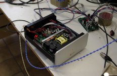
The DUT was still wired up on my bench so here's a picture. It's one of the cute boxes that we send to those selected customers I mentioned earlier. They contain an SMPS1200 and an NC1200. The SMPS is basically rectification + storage + chopper with synchronous secondary rectification. The latter could be of interest.
The DUT was still wired up on my bench so here's a picture. It's one of the cute boxes that we send to those selected customers I mentioned earlier. They contain an SMPS1200 and an NC1200. The SMPS is basically rectification + storage + chopper with synchronous secondary rectification. The latter could be of interest.
Attachments
Last edited:
- Status
- Not open for further replies.
- Home
- Amplifiers
- Class D
- Hypex Ncore