The module construction will be quite different from the UcD400, more like the OEM series modules (flat plate underneath the pcb). To mount it in an existing UcD400 app it'll need an L bracket. Not the most optimal from a thermal point of view but it looks like the NC400 will run a bit cooler than the UcD400.
The UcD400s really run a bit on the hot side considering their idle loss is specified as a mere 8W. I never found the blue T bracket to be an optimal solution. I understand Hypex was aiming at the 1U (44mm) rack space market, specifically internal heat sinks. The PCBs always stood out on my Ucd400ST boards and prevented a direct heat sink connection, though. I even had one module die on me under light load due to this.
A flat plate should be fine when mounted with some thermal grease. Personally, I prefer active speakers anyway.
2¢,
Sebastian.
A flat plate should be fine when mounted with some thermal grease. Personally, I prefer active speakers anyway.
2¢,
Sebastian.
Bruno,
Thank you for this. The patent does indeed demonstrate approaches applicable to high-order-loop class-AB amplifiers. In order to prove it to myself, I got a 7th-order-loop simulation, mostly behavioral, working based on ideas in the patent. (It clips cleanly!) Now I understand that continuous stability is possible, and can see the general approach for achieving it.
The mental breakthrough was to realize that removing a pole also means removing the zero and removing the gain the pair is shaping, as well. And it never would have occurred to me that clipping, shunting, or isolating a capacitor or network could so elegantly accomplish this.
Wonderful stuff. Thanks again.
You might see if the Ncore patent application supplies inspiration.
Thank you for this. The patent does indeed demonstrate approaches applicable to high-order-loop class-AB amplifiers. In order to prove it to myself, I got a 7th-order-loop simulation, mostly behavioral, working based on ideas in the patent. (It clips cleanly!) Now I understand that continuous stability is possible, and can see the general approach for achieving it.
The mental breakthrough was to realize that removing a pole also means removing the zero and removing the gain the pair is shaping, as well. And it never would have occurred to me that clipping, shunting, or isolating a capacitor or network could so elegantly accomplish this.
Wonderful stuff. Thanks again.
Yes just a few days ago Jan-Peter asked me to try and explain again how it works and as I put down the phone I wondered if it would have helped if I pointed out that zeros are eliminated as well...The mental breakthrough was to realize that removing a pole also means removing the zero(...)
The module construction will be quite different from the UcD400, more like the OEM series modules (flat plate underneath the pcb). To mount it in an existing UcD400 app it'll need an L bracket. Not the most optimal from a thermal point of view but it looks like the NC400 will run a bit cooler than the UcD400.
Supposing that NC400 is the name of the module to come,
does the naming convention implies that it will be capable
of 400W @ 4Ω like in the UcD series, or 400W @ 2Ω following
the NC1200 convention?
If the first case is valid then what will be the power output at 2Ω?
Bruno,
To clarify my confusion:
That the gain is also eliminated was the more difficult realization.
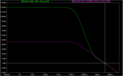
In the following hypothetical example, I now understand that the stable circuit would move from the GREEN 4-5th-order loop-gain to the MAGENTA first-order loop-gain (when divergence/error is detected.)

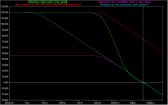
When I imagined "simply remove a few poles from the loop", I pictured the RED trace in the following graph. I intuitively understood the zeros were also eliminated, but I thought the remaining pole would be working on the same large gain. Clearly the RED loop-gain would be a disaster.

I also wonder if an alternate approach, switching in a dominant pole and switching out the high-order circuit (BLUE trace), is another potential solution.
If I'm "off in the weeds", please let me know. Otherwise, thanks again.
To clarify my confusion:
That the gain is also eliminated was the more difficult realization.
In the following hypothetical example, I now understand that the stable circuit would move from the GREEN 4-5th-order loop-gain to the MAGENTA first-order loop-gain (when divergence/error is detected.)

When I imagined "simply remove a few poles from the loop", I pictured the RED trace in the following graph. I intuitively understood the zeros were also eliminated, but I thought the remaining pole would be working on the same large gain. Clearly the RED loop-gain would be a disaster.

I also wonder if an alternate approach, switching in a dominant pole and switching out the high-order circuit (BLUE trace), is another potential solution.
If I'm "off in the weeds", please let me know. Otherwise, thanks again.
Bruno,
To clarify my confusion:
That the gain is also eliminated was the more difficult realization.
In the following hypothetical example, I now understand that the stable circuit would move from the GREEN 4-5th-order loop-gain to the MAGENTA first-order loop-gain (when divergence/error is detected.)
View attachment 229638
When I imagined "simply remove a few poles from the loop", I pictured the RED trace in the following graph. I intuitively understood the zeros were also eliminated, but I thought the remaining pole would be working on the same large gain. Clearly the RED loop-gain would be a disaster.
View attachment 229639
I also wonder if an alternate approach, switching in a dominant pole and switching out the high-order circuit (BLUE trace), is another potential solution.
If I'm "off in the weeds", please let me know. Otherwise, thanks again.
This is a nice explaination, very intuitive.
I found the biggest problem in switching the transfer functions whenever overload is detected is hiccup switching the transfers at recovery, which can last forever if gain reduction is too high.
Also if you detect the overload and reduce the gain and number of pole-zero pairs, the overload is no longer here in a moment. This is another possible hiccup situation.
darkfenriz,
Thanks for the hints. I'm sure there are 100 finer points, required for practical implementation, that I have yet to focus on. I'm just really excited about having been led to the general approach. (My one control systems class did not even hint at this approach.)
Thanks for the hints. I'm sure there are 100 finer points, required for practical implementation, that I have yet to focus on. I'm just really excited about having been led to the general approach. (My one control systems class did not even hint at this approach.)
I'd be in some trouble if it had...(My one control systems class did not even hint at this approach.)
Apart from that, control theory seems a blind spot in most curricula. I find that my greatest asset is not having studied it. I'm not one to suggest that going to school inevitably restricts ones intellectual freedom (mostly it liberates), but having been taught a subject badly can be a handicap.
... hiccup switching the transfers at recovery, which can last forever if gain reduction is too high. ... reduce the gain and number of pole-zero pairs, the overload is no longer here in a moment.
The patent mentions also, that the overall gain of both modes should be the same (in normal and reduced loop gain modes). This means, switching into lower loop gain mode, should not affect the overall gain of the amp, so the overload condition still stays here. Such behavior should help to avoid these hiccup modes then...

Sure, higher loop gain will slightly affect the overall gain also, but if in high loop gain mode the overall gain is also slightly higher, then switching into lower loop gain mode will even increase the absolute error signal for high order stage, which will prevent the hiccup switching.
Please, correct me if I am wrong.
A smidgen of a dB is a bit academic during clip.Sure, higher loop gain will slightly affect the overall gain also, but if in high loop gain mode the overall gain is also slightly higher.
- Status
- Not open for further replies.
- Home
- Amplifiers
- Class D
- Hypex Ncore
