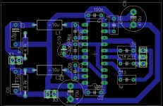
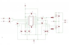
I recently made a TPA3122 pcb myself. However, when I try to use it, I just hear clicking sounds from the speakers. Also, when inspecting it with oscilloscope, looks like it's trying to start (voltage at output goes up for a moment and then goes down a few times in a second). The schematic is basically directly from the datasheet.
Any ideas?
Any ideas?
Attachments
Last edited:
/SD needs to be connected to VCC through a pullup resistor, 10K or so. Also, AGND and PGND are not connected to each other and you don't have output DC blocking caps. Were you trying to use a split supply? That's not going to work. The TPA3xxx chips only work with a single supply.
I'm using it in bridged mode, so no output capacitors are needed. AGND and PGND are connected to each other at power supply (I'm using two of the chips to make a stereo amp), should they be connected on the PCB instead?
Also, do you have to use a resistor between VCC and /SD?
Also, do you have to use a resistor between VCC and /SD?
Last edited:
I'm using it in bridged mode, so no output capacitors are needed. AGND and PGND are connected to each other at power supply (I'm using two of the chips to make a stereo amp), should they be connected on the PCB instead?
That's not the problem then.
How are you bridging them? Are you running a balanced signal?
Also, do you have to use a resistor between VCC and /SD?
I don't on my working boards.
BTW, the 4.7k resistors on the output aren't needed if you are running it bridged. They are only there to drain residual voltage on the blocking caps when the amp is powered off.
Last edited:
Did you check the s-by and the mute pins ?
Just checked it out and SD is high and mute low.
That's not the problem then.
How are you bridging them? Are you running a balanced signal?
Yeah, I turned the normal stereo signal into two balanced signals with an inverting opamp circuit. It has unity gain, so the plus input is straight from the potentiometer while the minus input is from the opamp.
Last edited:
BTW, the 4.7k resistors on the output aren't needed if you are running it bridged. They are only there to drain residual voltage on the blocking caps when the amp is powered off.
Hmm, the bridged output schematic in the datasheet had them, I don't know why.
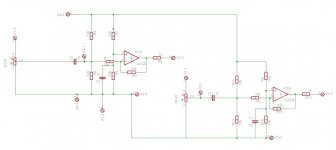
Have you tried playing the amp without the pre-amp circuit attached?
Try connecting one of the inputs to ground and playing a single ended signal through the other input. Still connect the load to both outputs just like BTL though.
Only half the bridge will play, the other half will just provide DC bias so you don't have to install blocking caps. That will at least tell you if the pre-amp circuit is causing a problem or not.
That's too far away. Your star ground should be at the chip, otherwise you may get secondary oscillations.AGND and PGND are connected to each other at power supply
Yes. That requires a current limited input and connecting directly to VCC is most likely causing your instability -- the chip heats up, shuts down, recovers, heats up, shuts down, etc.Also, do you have to use a resistor between VCC and /SD?
Yes. That requires a current limited input and connecting .directly to VCC is most likely causing your instability -- the chip heats up, shuts down, recovers, heats up, shuts down, etc.
Not really true. I have it connected directly to VCC on all of my boards and they work perfectly fine. You only need the resistor if you plan on using the shutdown function.
1. Most likely the TPA3xxx chips are built on MOS. The TI docs don't list breakdown voltages for any of the inputs, so there's a possibility some inputs are bipolar, especially noting that the max VCC is 36V. A 10K resistor eliminates any possibility that tying an input to VCC will current damage it.
2. There's 250KHz (give or take several KHz) ripple on VCC. If the inputs are MOS gates, that ripple feeds through. A 10K resistor will help filter that out. If you want to be really anal, you could put decoupling caps on all the logic inputs tied to VCC to eliminate any possibility of ripple feeding through.
2. There's 250KHz (give or take several KHz) ripple on VCC. If the inputs are MOS gates, that ripple feeds through. A 10K resistor will help filter that out. If you want to be really anal, you could put decoupling caps on all the logic inputs tied to VCC to eliminate any possibility of ripple feeding through.
Actually TI's datasheet does say that the allowed voltage for logic inputs is from -0.3 to Vcc +0.3..
I guess I could try adding a resistor to gain pins also, it just sounds unlikely that the problem is caused by it as others haven't used the resistors and got it to work fine.
I guess I could try adding a resistor to gain pins also, it just sounds unlikely that the problem is caused by it as others haven't used the resistors and got it to work fine.
Ah, you're right. I skipped right past it. That'll teach me not to speed read.
Your C3 and C4 are mono caps, yes? Those should absolutely be low esr, non-inductive caps.
Have you tried to see if it runs in single ended mode yet? Attach DC blocking caps to the output terminals and then to speakers, and attach the inputs to L and R.
Your C3 and C4 are mono caps, yes? Those should absolutely be low esr, non-inductive caps.
Have you tried to see if it runs in single ended mode yet? Attach DC blocking caps to the output terminals and then to speakers, and attach the inputs to L and R.
C3 and C4 are plastic capacitors, I don't know if they are low-esr or other special capacitors.
I haven't tried to run them in single ended mode, but I don't think it matters as the chips go offline if you even touch the inputs with anything, whether or not there is a load.
I haven't tried to run them in single ended mode, but I don't think it matters as the chips go offline if you even touch the inputs with anything, whether or not there is a load.
Single ended or BTL shouldn't matter.
I've built quite a few different PCB iterations using this IC and they have all worked (and I'm no professional by any means). Some had hum from bad grounding, but they did work.
I'm guessing it's either a layout problem or a capacitor problem. I used low ESR X7R ceramics for all the low value caps. You should try switching C3/C4 to >220nF X7R as close to the pins as possible.
I also used 2 layer PCB utilizing the second layer as a ground plane. Not sure if that played any role in my success rate or not.
- Status
- This old topic is closed. If you want to reopen this topic, contact a moderator using the "Report Post" button.
- Home
- Amplifiers
- Class D
- TPA3122 doesn't work