I'm VERY new to DIY amplifiers, but I did obtain a TI TPA3122D2 chip.
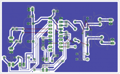
I've designed the board (attached) and powered it up using +15V DC.
Nothing happens. No hiss, no audio what so ever.
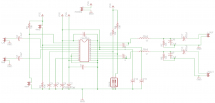
I'm wondering where I've made the error. I followed the reference design in TI's manual for the evaluation board, SLOU214A.pdf.
Any help would be appreciated.
Thanks!
Brian
I've designed the board (attached) and powered it up using +15V DC.
Nothing happens. No hiss, no audio what so ever.
I'm wondering where I've made the error. I followed the reference design in TI's manual for the evaluation board, SLOU214A.pdf.
Any help would be appreciated.
Thanks!
Brian
Attachments
Sorry to be lazy and check it for You, but..
-> Shutdown pin has to be pulled to high
mute pin has to be pulled to low
in order to make it work.
Make sure You done it.
You might want to remove the resistors and just solder the wires directly to gnd / vcc .
2 volts is the tripping voltage, might not affect anything but still worth a shot.
-> Shutdown pin has to be pulled to high
mute pin has to be pulled to low
in order to make it work.
Make sure You done it.
You might want to remove the resistors and just solder the wires directly to gnd / vcc .
2 volts is the tripping voltage, might not affect anything but still worth a shot.
SD and MUTE looks OK (amp should be ON with both switches/jumpers open). The power track going to pin10 looks way too thin, but should still work.
What's with C9 and C16 (should be inductors)?
I can't immediately make out any other mistakes that would keep it from working. The layout looks a bit poor; especially the ground fill.
I've built a handful of amps from these chips and they have all worked the first time. They seem almost bullet proof as well.
I used double sided board for mine, using the second side as a ground plane with no ground fill on the track side. Using a ground plane allowed the boards to be made without any jumpers.
Last edited:
C7 is *way* too far away from Pin1,Pin20. Remove your .1uF monolithic caps from their current locations. Solder .1uF mono caps right across Pin1-Pin20, Pin10-Pin11, and Pin7/8-Pin16/17.
Your power trace to PVCCR (Pin10) is too thin. Solder a 24G (or larger) wire from Pin10 to VCC.
I also recommend decoupling AVCC from PVCC through a small resistor (100-220 ohms is good). In my circuit I also increased the 10uF power cap on AVCC in the reference schematic to 100uF for greater immunity to drops in PVCC voltage.
And the ROUT trace in your PCB is too thin. This won't affect if the chip works or not, but LOUT/ROUT should be as thick as possible to minimize voltage drops in your audio out.
http://focus.ti.com/lit/ug/slou214a/slou214a.pdf
Use that as a guide, if it works for TI, it should work for you.
Use that as a guide, if it works for TI, it should work for you.
C7 is *way* too far away from Pin1,Pin20. Remove your .1uF monolithic caps from their current locations. Solder .1uF mono caps right across Pin1-Pin20, Pin10-Pin11, and Pin7/8-Pin16/17.
Your power trace to PVCCR (Pin10) is too thin. Solder a 24G (or larger) wire from Pin10 to VCC.
I also recommend decoupling AVCC from PVCC through a small resistor (100-220 ohms is good). In my circuit I also increased the 10uF power cap on AVCC in the reference schematic to 100uF for greater immunity to drops in PVCC voltage.
And the ROUT trace in your PCB is too thin. This won't affect if the chip works or not, but LOUT/ROUT should be as thick as possible to minimize voltage drops in your audio out.
Thanks for the advice. I clearly did not spend enough time studying TI's reference design when I did my board layout. I'm learning now that you can't rush this stuff. I'll try your recommendations.
Thanks for the advice. I clearly did not spend enough time studying TI's reference design when I did my board layout. I'm learning now that you can't rush this stuff. I'll try your recommendations.
It's not necessarily about not being able to 'rush' things. You can do things like this very quickly, the trouble here is that you need to learn good PCB design practice, which in itself can take a lot of time.
Pin 7/8 tied to ground?
According to the data sheet, pins 7/8 (analog ground) don't get connected to 0.1uF capacitors.
C7 is *way* too far away from Pin1,Pin20. Remove your .1uF monolithic caps from their current locations. Solder .1uF mono caps right across Pin1-Pin20, Pin10-Pin11, and Pin7/8-Pin16/17.
Your power trace to PVCCR (Pin10) is too thin. Solder a 24G (or larger) wire from Pin10 to VCC.
I also recommend decoupling AVCC from PVCC through a small resistor (100-220 ohms is good). In my circuit I also increased the 10uF power cap on AVCC in the reference schematic to 100uF for greater immunity to drops in PVCC voltage.
And the ROUT trace in your PCB is too thin. This won't affect if the chip works or not, but LOUT/ROUT should be as thick as possible to minimize voltage drops in your audio out.
According to the data sheet, pins 7/8 (analog ground) don't get connected to 0.1uF capacitors.
According to the data sheet, pins 7/8 (analog ground) don't get connected to 0.1uF capacitors.
He's just suggesting that the AVCC pins (17/18) are decoupled are closely as possible to the AGND pins (7/8). You can't get any closer than soldering the cap directly across the pins.
According to the data sheet, pins 7/8 (analog ground) don't get connected to 0.1uF capacitors.
At 250KHz switching frequency, you will get RF bleed into the analog section of the chip. A cap across the power supply of the analog section helps minimize this.
never used this chip, i just read the datasheet saying:
"MUTE Operation
The MUTE pin is an input for controlling the output state of the TPA3122D2. A logic high on this terminal causes
the outputs to run at a constant 50% duty cycle. A logic low on this pin enables the outputs. This terminal may be
used as a quick disable/enable of outputs when changing channels on a television or switching between different
audio sources."
so was thinking it needs to be logic low in order to enable the outputs.
I might had misunderstood something, english is not even close to my native, lol.
Logic high on /SD (through a 10K resistor) and logic low on MUTE will enable the outputs. In aviatorbja's schematic, he should leave both SW1 and SW2 open to enable output.so was thinking it needs to be logic low in order to enable the outputs.
Yes, I have measured pin 2 at 15Volts and Pin 3 at 0 volts. I'll try re-arranging things on the board (0.1uf caps) and see if that helps.
If you need any pin voltage readings for reference just let me know, I'll dig one of my boards out.
If you need any pin voltage readings for reference just let me know, I'll dig one of my boards out.
Thanks, I will implement killerbobjr's suggestions on cap placement and pin 10 supply this weekend. I will take some readings from input and output pins.
Also, any recommendations on a power supply for this unit? Right now, I'm using a rather massive +15V regulated benchtop power supply.
This forum is excellent. SO much information to be had.
I really appreciate it.
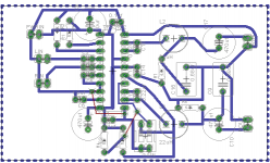
Amp now working.
Wanted to follow up on this. Finally got a chance to re-design the board and re-assemble with the new board. Amp works fine now. Very quiet. I need to test out on a better pair of speakers, but so far the amp sounds quite good. I'm using 15V DC power supply.
new board design is attached.
Thanks again!
Attachments
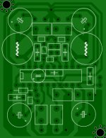
Clicking Sound...
I Tried to build TPA3122, but it is making click-click sound..
Layout is attached...What could be the problem?
Kindly help..component valus as given in the datasheet.
Thanks in advance...
According to the data sheet, pins 7/8 (analog ground) don't get connected to 0.1uF capacitors.
I Tried to build TPA3122, but it is making click-click sound..
Layout is attached...What could be the problem?
Kindly help..component valus as given in the datasheet.
Thanks in advance...
Attachments
- Status
- This old topic is closed. If you want to reopen this topic, contact a moderator using the "Report Post" button.
- Home
- Amplifiers
- Class D
- TPA3122 - not working. Nothing