Hi again
Now i have all the parts. unfortunately this wonderfull case i got just a few days ago i do need to drill holes. Now i have on the left and right side a very heavy ( i guess about 8cm) heatsink. My question is if it is possible to use a glue (which one?) or silicone (for higher temperatur) to put the small Hypex Modules UCD 400 on these heatsinks. What do you mean, is this a good idea or are the modules to "hot" to fix with glues?
Thanks a lot for an idea or any recommandations.
Souldriver

Don't glue the modules to a heatsink. If the heatsink is too thick for the screws supplied with the modules, get longer screws or use small bolts and drill out the mounting hole threads so the bolt will fit. Use a silicon thermal paste between the heatsink and module.
While these modules DO need to be heatsinked, they don't need very big ones, and an aluminum case is usually sufficient by itself, a heatsink is even better if it's sized right.
Retraction: I have noticed after some time now that there is indeed a surge when the SMPS I am using are powered up, it just took some time to notice. A soft start circuit for use in applications where voltage dips can't be tolerated would probably be a good idea.
thanks a lot for answering
what do you mean? Is it not possible to only use a kind of silicon (-glue). i read somewhere that this could be a possibility to fix the modules because silicon can go till 300 celsius. i know that the hypexmodules do not need a large heatsink, but it is more a question of how to fix than how get the best results in cooling.
does silicon work (without bolts and screws). Or binding posts could be a possibility too, isnt it?
Thanks for giving me your advises.")
what do you mean? Is it not possible to only use a kind of silicon (-glue). i read somewhere that this could be a possibility to fix the modules because silicon can go till 300 celsius. i know that the hypexmodules do not need a large heatsink, but it is more a question of how to fix than how get the best results in cooling.
does silicon work (without bolts and screws). Or binding posts could be a possibility too, isnt it?
Thanks for giving me your advises.
thanks a lot for answering
what do you mean? Is it not possible to only use a kind of silicon (-glue). i read somewhere that this could be a possibility to fix the modules because silicon can go till 300 celsius. i know that the hypexmodules do not need a large heatsink, but it is more a question of how to fix than how get the best results in cooling.
does silicon work (without bolts and screws). Or binding posts could be a possibility too, isnt it?
Thanks for giving me your advises.
Any kind of glue I would think would be unreliable in the long term. As far as thermal conductivity I have no idea what's available and how well it works. If the layer used is extremely thin it would probably work until it fell off. Just my 2 cents.
Glue is not a good idea. It must be screwed on for a really tight thermal contact with the heatsink or case. An alternative would be to somehow clamp it down with enough pressure, the way you mount the cooler on the CPU-chip in the PC. Also use a thin layer of arctic silver or similar thermal paste for good contact.
The project is finished...almost :-(
Now, everything is complete and my first amp project should be finished...should. There is no sound at all..
So, the powerconnection works but there is no sound even no noise. i guess that the ucd's do not work
1. The power/electric should work because the smps make little "clic" when i put it on.
2. The push button is allways lighning when i switch the power on but nothing happens when i push it...(do i have it connected right?)
3. The little Molex ground cable is connected to second black wire (ground) on the Smps
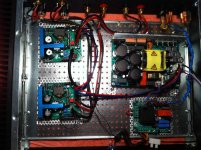
Does anyone have idea why it does not work? I put some pictures just below. If somebody could check the connections this would be very fine.
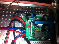
Now, everything is complete and my first amp project should be finished...should.
There is no sound at all..So, the powerconnection works but there is no sound even no noise. i guess that the ucd's do not work
1. The power/electric should work because the smps make little "clic" when i put it on.
2. The push button is allways lighning when i switch the power on but nothing happens when i push it...(do i have it connected right?)
3. The little Molex ground cable is connected to second black wire (ground) on the Smps
Does anyone have idea why it does not work? I put some pictures just below. If somebody could check the connections this would be very fine.
Attachments
Hi Javin
Thanks a lot for answering. Yes there is definitely a tight termal contact. The UCD's are screwed with the case. The only thing what i had to do is to use a kind of alluminium template but they are screwed very tight with the case. Is there a possibilty to find out if the ucd's are killed (hopefully not!!!) I really take care about them!
Did you had a look for the connections? Is everything ok?
Thanks again Javin!
Thanks a lot for answering. Yes there is definitely a tight termal contact. The UCD's are screwed with the case. The only thing what i had to do is to use a kind of alluminium template but they are screwed very tight with the case. Is there a possibilty to find out if the ucd's are killed (hopefully not!!!
) I really take care about them!Did you had a look for the connections? Is everything ok?
Thanks again Javin!
Hi Javin
Thanks a lot for answering. Yes there is definitely a tight termal contact. The UCD's are screwed with the case. The only thing what i had to do is to use a kind of alluminium template but they are screwed very tight with the case. Is there a possibilty to find out if the ucd's are killed (hopefully not!!!
Did you had a look for the connections? Is everything ok?
Thanks again Javin!
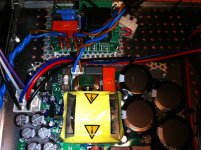
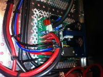
Hold on a minute. I see the modules screwed to the case, but I do not see the blue aluminum heat sink block in contact with anything. It looks to me like you have no heat sink at all. The face of the blue aluminum block on the module needs to be flat against the metal case. Just screwing the boards to the case will not work. It does nothing for heat dissipation.
The modules have thermal protection so you probably didn't ruin them. Make certain that the control wire is grounded and check the power supply voltages at the module terminals to make sure the power is there. Static electricity will easily damage the modules, but failing to provide a heat sink and powering them up should not hurt them. They may simply be too hot and shut down. Try letting the amp cool off completely, then apply an input source and then apply power with the amp on. It should run at least a short time before shutting down. If that doesn't work something else is wrong too.
If you've double checked for shorts both in the module mounting, power supply and audio input (I'd also recommend double checking all power connections and jumper options) I would try the following:
it looks like you've connected the UCD enable pins to the SMPS J1.6 "Output Ground Bootstrap" (Having used the linear supplies myself I've no clue what the bootstrap connections are on these.) I recommend you either tie the UCD enable to the standard ground, or the the SMPS J4, pin 6 - which is the connection designed to enable the the UCD's
from the datasheet:
"When the enable-line of a UcD-series amplifier is connected to this pin the amplifier will be enabled and disabled automatically when the SMPS1200 is switched on and off preventing unwanted audio artefacts during powerup and powerdown."
unfortunately there is an error in the SMPS1200 datasheet. Pages 6 and 9 disagree as to whether it is J4 pin 5 or 6. Luckily the other pins are listed as NC (no connect) so it should be safe to try both.
for test purposes, it should be OK to simply attach that UCD enable line to any good, known ground. Including the chassis if it is grounded. If the UCD gets power and is enabled, it'll light up like a christmas tree with those HxR's on there, so you'll know if it's powered.
Hi everybody
Thanks for your help. I definitely need it i really appreciate that a lot.
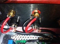
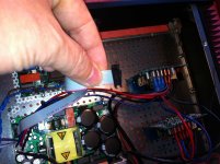
So, now i have two wire plugs:
- on the first picture is J4
- the second picture is J6
But i have no idea how i have to connect these wire plugs. There is no other possibility to put these plugs on the UCD or i am wrong?
How do i have to connect Smps with the UCD's to enable them and where is this pin?
Thanks again!
Thanks for your help. I definitely need it
i really appreciate that a lot.So, now i have two wire plugs:
- on the first picture is J4
- the second picture is J6
But i have no idea how i have to connect these wire plugs. There is no other possibility to put these plugs on the UCD or i am wrong?
How do i have to connect Smps with the UCD's to enable them and where is this pin?
Thanks again!
Attachments
Last edited:
When the amp modules where screwed to the base (before you turned them over and mounted the blue heat sink to the base), there they in direct contact with the base or elevated by posts or washers? If they where in direct contact you may have shorted out the board?
I can know see they look like they where elevated, but not by much.
I can know see they look like they where elevated, but not by much.
Last edited:
But i have no idea how i have to connect these wire plugs. There is no other possibility to put these plugs on the UCD or i am wrong?
The plugs are designed to mate with the UCD700 IIRC. For the 400 you can't use the plugs that came with the smps. You'll need to locate the correct wire and connect to the UCD by other means. Since you have the ribbon cable (with IDC connectors), you can use the end that connects to the SMPS, but cut and strip the right wire for the UCD enable/turn-on pin.
For test, I recommend just ground the UCD enable pins and see if they power on. Then figure out how you'd like to permanently attach them.
Hi everybody
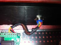
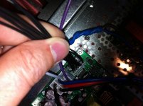
Just noticed, I think your softstart is miswired. Input is OK, output to the SMPS is not on the right pins. (your enable pin wiring maybe OK after all)
see pic.
the click you hear now at power-on is the relay in the softstart. I'm pretty sure your SMPS is not getting power. (this is where a multimeter comes in handy)

Last edited:
Now again, is this correct when i try to get from the plug J4 pin 5 or 6 and connect it to the ground (case?) and after that it should work....hopefully!!!
you might be fine the way you had it the enable pin connected already. Do let us know, but your only issue may have been the AC supply.
What I am referring to with SMPS J4 pin 5 (or 6) is that it be connected to the UCD J1, pin 4 (the "ON/OFF Control" pin) It is fine if you simply ground this J1.4 pin, but the SMPS has a dedicated output signal on J4 Pin 5 (or 6) that is designed to turn on the UCD after the SMPS is stable.
So either leave SMPS J4 disconnected, or wire pin 5 or 6 to the UCD control pin. Hopefully this makes sense now.
Before spotting the AC misconnection at the softstart, I was not sure if the wire you attached the UCD J1.4 was a good ground. It maybe just fine.
Let us know if you're UCD's power up OK...
- Status
- This old topic is closed. If you want to reopen this topic, contact a moderator using the "Report Post" button.
- Home
- Amplifiers
- Class D
- Guide to build Hypex Modules