hello, i have a Ground Zero GZPA 1.4000D it is a class D mono using IRFP264 in the output ...
after some trouble with a 220nf capacitor on the input side i blew a irfp264 (leaving the amplifier on without a heatsink for a lot of time does that )
)
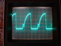
i replaced all outputs with irfp4229 and looking with a scope on the gate it looks like this it should be a square wave ?? it actualy looks like a triangle ...
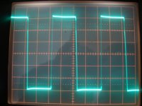
the output of the fets is square....
i did apply power and loaded it on 1 ohm woofer playing music and it blew when i turned the volume up ... at about 1000-1500W ...
all irf3205 are dead and 2xirfp4229 ... i replaced the irf3205 and it works again ... any ideas on why did it die ?
the scope in the first pic is 2v/div ...
after some trouble with a 220nf capacitor on the input side i blew a irfp264 (leaving the amplifier on without a heatsink for a lot of time does that
) i replaced all outputs with irfp4229 and looking with a scope on the gate it looks like this
it should be a square wave ?? it actualy looks like a triangle ... the output of the fets is square....
i did apply power and loaded it on 1 ohm woofer playing music and it blew when i turned the volume up ... at about 1000-1500W ...
all irf3205 are dead and 2xirfp4229 ... i replaced the irf3205 and it works again ... any ideas on why did it die ?
the scope in the first pic is 2v/div ...
Attachments
Last edited:
any ideas on why did it die
Because something was wrong.
If you showed a (partial) schematic and some other detail maybe I could be more specific.
Some interesting details:
- gate driver circuit (maybe it's partially damaged)
- supply voltage
I figured out that the configuration is half bridge with 5 MOSFETs paralelled (originally).
Interesting gate drive signal.
Could be they have a resistor on/ diode off circuit in which case the gate on drive will be a bit slower to stop cross conduction.
My class d amp has a square wave going to the mosfet gates but has deadtime programmable in the chip.
We really need a circuit diagram to help constructively.
Could be they have a resistor on/ diode off circuit in which case the gate on drive will be a bit slower to stop cross conduction.
My class d amp has a square wave going to the mosfet gates but has deadtime programmable in the chip.
We really need a circuit diagram to help constructively.
i don`t have the schematics ... i was hoping that some one has a schematic of a similar amp or can tell me the gate drive signal is good or bad... i`m thinking is bad , all the amps i have seen use square wave to turn on and off fets.
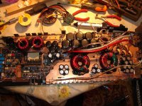
this amp uses discrette driver i have attached it . the whole driver board is very simple (i was expecting a lot more). uses an resiston and a diode to turn on and off the mos-fet ... i will check tomorrow but i think it was a 100ohm resistor and a diode to turn it off . isn`t 100 ohm a little high value ? i was expecting 10ohm or lower...
this amp works on +/-91V regulated supply with minimum 1ohm load i`ve done 0,7ohm with no problem and only 8 output devices (IRFP264)
the amp uses an resiston and a diode to turn on and off the mos-fets.
Attachments
isn`t 100 ohm a little high value ?
Yes, absolutely!
Check low side gate driver against the high side one, because it seems to be correct!
Last edited:
Waveforms look perfectly normal for car-subwoofer grade class D. Were you expecting something better?
100 ohms is not a low value, but the first limiting factor for "switching speed" is PCB layout, MOSFET limitations (like body diode limits) only play a secondary role in that kind of amplifiers.
In fact, sad truth is that you may manage to make it work with IRFB4229 by further increasing gate resistors to 150 or 220 to reduce di/dt to the levels that the PCB can tolerate without EMI becoming self-destructive Reducing gate supply voltage a bit (keep it >9V) does have the same effect but it has to be done with care because other parts of the circuit could be disturbed.
Note that, although IRFP4229 is quite similar to IRFP264, it has 2 to 3 times higher transconductance than IRFP264 resulting in about 1.5 to 2 times higher di/dt (transconductance is higher but input capacitance is also a bit higher too).
Driving the gates with square-like waves only makes sense in resonant circuits (like in a push-pull SMPS with proper dead time) or when there is other means to control di/dt.
100 ohms is not a low value, but the first limiting factor for "switching speed" is PCB layout, MOSFET limitations (like body diode limits) only play a secondary role in that kind of amplifiers.
In fact, sad truth is that you may manage to make it work with IRFB4229 by further increasing gate resistors to 150 or 220 to reduce di/dt to the levels that the PCB can tolerate without EMI becoming self-destructive
Reducing gate supply voltage a bit (keep it >9V) does have the same effect but it has to be done with care because other parts of the circuit could be disturbed.Note that, although IRFP4229 is quite similar to IRFP264, it has 2 to 3 times higher transconductance than IRFP264 resulting in about 1.5 to 2 times higher di/dt (transconductance is higher but input capacitance is also a bit higher too).
Driving the gates with square-like waves only makes sense in resonant circuits (like in a push-pull SMPS with proper dead time) or when there is other means to control di/dt.
i did apply power and loaded it on 1 ohm woofer playing music and it blew when i turned the volume up ... at about 1000-1500W ...
mounting problem,your clips is to large !!!
An externally hosted image should be here but it was not working when we last tested it.
Waveforms look perfectly normal for car-subwoofer grade class D.
Are you sure? Notice that falling and rising edge on output are very different! This can't be normal! If the slow one is normal, then the fast one is not.
edit:
With R192=220 ohms the gate waveform is understandable, but what kind of idiot place there such a high resistor there?
Last edited:
Are you sure? Notice that falling and rising edge on output are very different! This can't be normal! If the slow one is normal, then the fast one is not.
I was talking about the gate waveform. It's true that the fast rising edge in the switching waveform is telling "risk of overlap, more dead time on that side please", while the other looks more or less right (could use less dead time).
However, have you ever repaired one of these? They are intended for LF output only, >250Hz, switching frequency is usually in the 50khz range, and the discrete gate drivers they use are ugly. Many use electrolytic capacitors in the output filter, and nearly all use either pre-filter feedback or no feedback at all
So what I mean is that good symmetry is not even attempted, and at the low di/dt rates they operate (mandated by dumb PCB and junk MOSFET) overlap for a few dozen ns is not really a problem. They may take a whole microsecond of overlap to develop destructive currents.
Last edited:
In fact, sad truth is that you may manage to make it work with IRFB4229 by further increasing gate resistors to 150 or 220 to reduce di/dt to the levels that the PCB can tolerate without EMI becoming self-destructive
If this is really the root of the problem, then IMHO it would be better to improve PCB by adding some wires and capacitors. (Given the much better FETs the diode cross conduction problem has been eased, so lower stray inductance won't cause too high current peaks.)
Last edited:
If this is really the root of the problem, then IMHO it would be better to improve PCB by adding some wires and capacitors. (Given the much better FETs the diode cross conduction problem has been eased, so lower stray inductance won't cause too high current peaks.)
Adding capacitors results in ringing, then you have to add snubbers (and fit everything), then something else is no longer up to the job, then something else has to be improved too, and the loop goes on until you get really fed up.
I think the original poster just wanted to make it work again, clumsy as it was when it left the factory.
However, have you ever repaired one of these? They are intended for LF output only, >250Hz, switching frequency is usually in the 50khz range, and the discrete gate drivers they use are ugly.
I haven't met with these, but a switching event lasts for some microseconds sounds to be a nightmare for me. And with the original MOSFETs it must have been much worse. With 4*50 nC miller charge the switching transient must have been more then 10 us long. This would be almost fully linear operation, not ClassD!
Last edited:
Adding capacitors results in ringing, then you have to add snubbers (and fit everything), then something else is no longer up to the job, then something else has to be improved too, and the loop goes on until you get really fed up.
Why would a supply decoupling capacitor made it worse?
I think the original poster just wanted to make it work again, clumsy as it was when it left the factory.
Yes, but I suppose it was ClassD! I try to figure out what could the charging resistance could really be. If it is 100 ohms per gate, then OK, it is usable, but more then 220 ohms for all of the paralelled devices is unreasonable.
as mgm2000ro said the clamps that hold the fets to the heatsink might be the problem ... i hate these things .. in the next test i will use an external +/-90V power source and external heatsink for the irfp4229 and see what happens
i can not afford blowing another 20xIRF3205 it isn`t cost effective ...
Eva you are right i just want to make it work but if it can be improved ... i would like that because it is my personal amplifier ...
i can not afford blowing another 20xIRF3205 it isn`t cost effective ...
Eva you are right i just want to make it work but if it can be improved ... i would like that because it is my personal amplifier ...
what can change to improve this schematic?
http://img854.imageshack.us/img854/1314/biguv.jpg
An externally hosted image should be here but it was not working when we last tested it.
http://img854.imageshack.us/img854/1314/biguv.jpg
Last edited:
Turn-on current is the range of 80 to 100mA, while total gate charge is around 500nC. Simple calculation gives a total turn-on time of around 5-7us for around 20us period.
Ergo: the wavaforms look perfectly like the 'designer' wanted them to.
Good news is mosfets are pretty forgiving here, the 99% of transition takes probably more like 1.5 to 2us, the rest is sub-threshold charge and post-miller charge. The first makes no harm at all, the latter results in just a bit higher effective Rdson.
I haven't met with these, but a switching event lasts for some microseconds sounds to be a nightmare for me. And with the original MOSFETs it must have been much worse. With 4*50 nC miller charge the switching transient must have been more then 10 us long. This would be almost fully linear operation, not ClassD!
Well, you get the idea now, but switching events don't last that long, a few hundred nanoseconds would be more accurate. Yes, charging the gate to the full drive voltage can take a few microseconds, but IRFP4229 is already fully on at 6.5V and IRFP264 is similar, so it's not that bad.
Consider that the PCB is good only up to 50A/us per MOSFET or so, so building up the current has to take some time (achieved just with 100 ohm gate resistors and relying on finite transconductance). Not much to do with our >500A/us switching.
Last edited:
edit:
With R192=220 ohms the gate waveform is understandable, but what kind of idiot place there such a high resistor there?[/QUOTE]
Cheap cross conduction limiting? Though with that much resistance there's really no need to double the NPN drivers. Is that a verified resistance value?
You might be able to get away with things at 55kHz that just wont go at 550kHz, if you're used to looking at full bandwidth switching amps.
Last edited:
- Status
- This old topic is closed. If you want to reopen this topic, contact a moderator using the "Report Post" button.
- Home
- Amplifiers
- Class D
- GZPA Class D 4000W with IRFP264