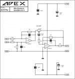
Balanced input and preamp for D200.
This is what i'm looking for.
Regards
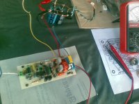
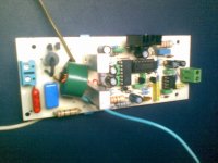
My D200.2 ready for testing
Hi sir Mile, can i use 74LS00 instead 74AC00
Hi sir Mile, can i use 74LS00 instead 74AC00
An externally hosted image should be here but it was not working when we last tested it.
Hi sir Mile, can i use 74LS00 instead 74AC00

Nice work, use 74HC00 or 74HCT00
Regards
My working D200 (I used D200.2 board)
At +-27vdc PSU my setup was;
TIP41C and 12v zener for the regulator.
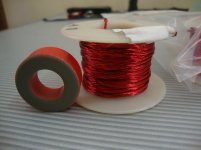
About 30t of AWG#18 at T106-2 output inductor.
IRF640N output fets.
Sound is very good and best by using Litz wire on T106-2 (just filled the entire core without overlapping the wires) but Fets IRF640N and 10ohm zobel heats up real fast.
Sir Mile, how do I control overheating of 10ohm zobel?
Many thanks!
At +-27vdc PSU my setup was;
TIP41C and 12v zener for the regulator.
About 30t of AWG#18 at T106-2 output inductor.
IRF640N output fets.
Sound is very good and best by using Litz wire on T106-2 (just filled the entire core without overlapping the wires) but Fets IRF640N and 10ohm zobel heats up real fast.
Sir Mile, how do I control overheating of 10ohm zobel?
Many thanks!
Attachments
Use 1k pot instead 510R and set... use TIP31 instead IRF640 for 12V bias regulator.My working D200 (I used D200.2 board)
At +-27vdc PSU my setup was;
TIP41C and 12v zener for the regulator.
About 30t of AWG#18 at T106-2 output inductor.
IRF640N output fets.
Sound is very good and best by using Litz wire on T106-2 (just filled the entire core without overlapping the wires) but Fets IRF640N and 10ohm zobel heats up real fast.
Sir Mile, how do I control overheating of 10ohm zobel?
Many thanks!
Last edited:
^..adjust the carrier frequency, 
Thanks Sir Mile!
Hi! remle,
Good to hear that, well that reminds me ..guess I'll have to check my output coil I think I haven't tested with 47turns.
Regards!
Thanks Sir Mile!
Hi abetir (kabayan)
My D200.2 is working now after replacing 74LS00 with 74HC00
As per sir Mile suggestion my supply voltage is +/- 50V
IRF640N is warm not hot and 10 ohm zobel also warm after 30 minutes but not hot
I also using T106-2 with 47 turns AWG#20 magnet wire
Hi! remle,
Good to hear that, well that reminds me
..guess I'll have to check my output coil I think I haven't tested with 47turns. Regards!
edit
Hello Apex,
D200 rev. lay-out don't have 100nf/100v near the resistor 4.7k/2watt, while the lay-out of D200.2rev has and what the different in adding 100nf in D200.2?
DC,
To my knowledge the additional 100nf from versions D200.1 & D200.2 serves as bootstrapping cap supposedly as an added compensation to prevent failures (when driving changes in freq) of IR2110 fet driver...not an expert opinion though
BTW How was your D200 build?
Regards!
DC,
To my knowledge the additional 100nf from versions D200.1 & D200.2 serves as bootstrapping cap supposedly as an added compensation to prevent failures (when driving changes in freq) of IR2110 fet driver...not an expert opinion though
BTW How was your D200 build?
Regards!
hello sis abetir,
my d200 turbo still pending, I've pull out the inductor and i use it in my other project, sis can you send me a files or any PDF of your D200.. thanks..
DC,
I used the earlier lay-out by Apex for D200.2, just flip the image using photoshop (for ironing). I added track extension to accomodate the input and output terminals prior to etching. I do think Thien's lay-out is also great, I do however noted that in Thien's lay-out the RC Low Pass Filter was changed into 5ohm/100n. Zobel resistor was 10ohm in parallel, that becomes 5ohm(original was 10ohm/220n. The output 220n caps was also changed into 100n (104).
I would be very cautious about this because cut of frequency and time constant changes, this could result into instabilities or parts abnormal heating. For the Low Pass Filter I have tried RC 5.6ohm/100n, and the resistor gets overheated. Unless other builder has tried Thien's changes without causing troubles.
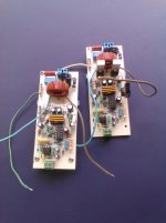
In my final build I have changed 510ohm to 680ohm (set it thru 1k trimmer adjust) heat dissipation over 10ohm zobel resistor vanished. My rail PSU was +-27vdc. 47t on T106-2 of AWG#20. I do think the best wire for the T106-2 was Litz wire , because the mid & highs improves dramatically. I came across this paper about the method of winding wires on Class D output inductor, air gapping is important and best to avoid overlapping of wires. I could say that the material used for the inductor greatly affects sonic quality. I even tried those green toroids with about 4t of AWG#18 without air gap (ferrite material). It works but it hardly finished a 3mins song, the core gets saturated real fast (overheating)
I played my amp for 2hrs with varying musicalities Jazz Pop Metal, output fet and the inductor barely get warm, but for the bias regulator a heatsink is a must. Use the best output inductor than you can get, you will be pleased with the results.
I used the earlier lay-out by Apex for D200.2, just flip the image using photoshop (for ironing). I added track extension to accomodate the input and output terminals prior to etching.
I do think Thien's lay-out is also great, I do however noted that in Thien's lay-out the RC Low Pass Filter was changed into 5ohm/100n. Zobel resistor was 10ohm in parallel, that becomes 5ohm(original was 10ohm/220n. The output 220n caps was also changed into 100n (104).I would be very cautious about this because cut of frequency and time constant changes, this could result into instabilities or parts abnormal heating. For the Low Pass Filter I have tried RC 5.6ohm/100n, and the resistor gets overheated. Unless other builder has tried Thien's changes without causing troubles.
In my final build I have changed 510ohm to 680ohm (set it thru 1k trimmer adjust) heat dissipation over 10ohm zobel resistor vanished. My rail PSU was +-27vdc. 47t on T106-2 of AWG#20. I do think the best wire for the T106-2 was Litz wire
, because the mid & highs improves dramatically. I came across this paper about the method of winding wires on Class D output inductor, air gapping is important and best to avoid overlapping of wires. I could say that the material used for the inductor greatly affects sonic quality. I even tried those green toroids with about 4t of AWG#18 without air gap (ferrite material). It works but it hardly finished a 3mins song, the core gets saturated real fast (overheating) I played my amp for 2hrs with varying musicalities
Jazz Pop Metal, output fet and the inductor barely get warm, but for the bias regulator a heatsink is a must. Use the best output inductor than you can get, you will be pleased with the results. Attachments
DC,
I used the earlier lay-out by Apex for D200.2, just flip the image using photoshop (for ironing). I added track extension to accomodate the input and output terminals prior to etching.
I would be very cautious about this because cut of frequency and time constant changes, this could result into instabilities or parts abnormal heating. For the Low Pass Filter I have tried RC 5.6ohm/100n, and the resistor gets overheated. Unless other builder has tried Thien's changes without causing troubles.
In my final build I have changed 510ohm to 680ohm (set it thru 1k trimmer adjust) heat dissipation over 10ohm zobel resistor vanished. My rail PSU was +-27vdc. 47t on T106-2 of AWG#20. I do think the best wire for the T106-2 was Litz wire
I played my amp for 2hrs with varying musicalities
thanks sis abetir for your tips... very much appreciated sis..
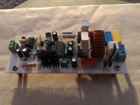
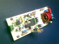
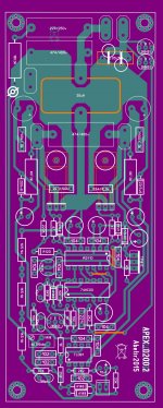
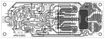
I find this amp quite interesting, having a beginner knowledge of Class D. I tried my hands on doing a revised lay-out, just like the rest who were mesmerized by this amp . I do think the board size has become a bit bigger in order to accomodate larger output caps (470n/400v & 220n/400v), easier to find here in my place. Not final yet, but I will be sharing the pdf files with Sir Mile's approval The other picture was my build using Apex D200.2 lay out.
Sir Mile,
Can you point me to a post that has wiring instructions for this amp?
Many Thanks!
. I do think the board size has become a bit bigger in order to accomodate larger output caps (470n/400v & 220n/400v), easier to find here in my place. Not final yet, but I will be sharing the pdf files with Sir Mile's approval The other picture was my build using Apex D200.2 lay out.Sir Mile,
Can you point me to a post that has wiring instructions for this amp?
Many Thanks!
Attachments
Sir Mile,
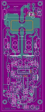
Is this new lay-out good enough? Some modification was made, notably an additional small filter cap for the + & - rail supply (size is around 47-100uf 63/100v) and another 104 caps as snubber. This is not meant as an added boost to the rail supply but to compensate for the extended tracks of the output fets. Another thing was 74HC00 is now placed horizontally with IR2110, not sure if this is a good idea, but I do think that some tracks was shortened. The input opamp voltage supply ground was separated from the feedback node ground.
Many thanks!
Attachments
Sir Mile,
Is this new lay-out good enough? Some modification was made, notably an additional small filter cap for the + & - rail supply (size is around 47-100uf 63/100v) and another 104 caps as snubber. This is not meant as an added boost to the rail supply but to compensate for the extended tracks of the output fets. Another thing was 74HC00 is now placed horizontally with IR2110, not sure if this is a good idea, but I do think that some tracks was shortened. The input opamp voltage supply ground was separated from the feedback node ground.
Many thanks!
Nice work, what is size of ypur pcb? You can add balanced input from post #661.
Regards
Last edited:
hello Apex
D200 voice breaks when up the volume to hight. IR work with 11.4V. Power supply +-56V, use fet IRFP4227.
What is resistors value in overload protect circuit?
Nice work, what is size of ypur pcb? You can add balanced input from post #661.
Regards
PCB was 60mm (width) 155mm (height) still larger than the original but I guess small enough to fit in place those large output MKP caps.
Many thanks!
Hi Apex.What is resistors value in overload protect circuit?
All value Part as Thienchay's PCB layout
Attachments
- Home
- Amplifiers
- Class D
- Class D Amp with LM566, LM393 and 2XIRF530