Hi Dacz,
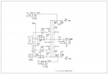
Remove R13&R12 and R11 is 1K/2W C25 is 100pF/100V R21&R20 is 6K8/2W R14 change to 60K (Parallel 100K & 150K) and Remove C2, R2 is 1K2 remove R23 & Provide Zener 15V parallel C13 & L1 is 22uH, 0.22uF/400V use C27 Parallel & .Now the audio will good & use 330R/2W series with Q4 Collector { Now you can use IRFP250N}.
Regards
MANOJ
Sir Manoj,
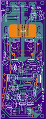
Could you confirm to this lay-out if the changes you made is correct?
Highlighted in orange color. Also, is this mod device specific like, it can only be used with IRFP250N as output fet?
Thanks!
Attachments
Has anyone made a comparable measurements between using gapped EE flyback traffo & iron powders as output inductors? I made some listening test and it seems, the gapped EE ferrite performs really good as well. It is definitely cold probably colder than the T106-2. I experimented another EE same size as flyback traffo but ungapped, I did however made a 1mm gap on one leg and it surprisingly performs very good as well.
..correction: ETD cored ferrite not EE

Last edited:
I also use some EE and ETD cores with gap, what about sound?
Regards
Sir Mile,
How many turns of wires using flyback traffo to get 30uH? Sorry don't have an inductor meter here, i'm relying from online calculators and I can't find one that calculates ETD or EE cores...
Many Thanks!
Sir Mile,
How many turns of wires using flyback traffo to get 30uH? Sorry don't have an inductor meter here, i'm relying from online calculators and I can't find one that calculates ETD or EE cores...
Many Thanks!
use transfomer design tool can calculate both for smps and inductor
^Many thanks Stewin, that's a lot of help....page bookmarked 
...ok will edit another draft.
Hi abetir,
Remove track +75v to ZD15v and add 2k2/2w to GND on SPK out
VR resistor use/set 600R ( 1K + 1K5)
Regards
MANOJ
...ok will edit another draft.
I've been reading some technical papers on the Fringing flux and its side effects on ferrite inductors. Possible solution states;
1. gap should be made at a minimum (not too large).
2. wind the wire closer to the core covering the gap. (no bobbin).
3. keep the winding's away from the gap.
4. wrap a piece of copper screening on the gap.
Excepting no. 3 all the suggested soution said to keep the fringing field at a minimum and forces the exiting force back to its path.
Anyone has tested this method? I do think that for hardcore DIY'er, (those who want to get dirt on their hands) This is one excellent solution as Iron powders can sometime be expensive and hard to find in some areas.
1. gap should be made at a minimum (not too large).
2. wind the wire closer to the core covering the gap. (no bobbin).
3. keep the winding's away from the gap.
4. wrap a piece of copper screening on the gap.
Excepting no. 3 all the suggested soution said to keep the fringing field at a minimum and forces the exiting force back to its path.
Anyone has tested this method? I do think that for hardcore DIY'er, (those who want to get dirt on their hands
) This is one excellent solution as Iron powders can sometime be expensive and hard to find in some areas.
Last edited:
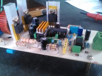
I converted one of my ApexD200.2 board to Manoj modification for a test run.
For my +-27vdc linear PSU my set up was;
510 + 100 ohm (series connect) for freq. oscillator, reads 605ohm in my DMM.
100k + 150k (parallel connect) for feedback, reads 58.8k in my DMM.
270ohm 2w limiting resistor for TIP41C collector to ground.
1k2 1w for feedback, should be 1k 2w but don't have it around.
3k3 2w current source for Opamp input supply (6k8 2w for +-75v rail).
Other mods are under the board, that is 2k2 2w ground to speaker out, comprising of LPF.
15v zener in parallel with supply & feedback bypass caps
of IR2110 and 224/250v in parallel with fets +- rail voltage (original was 474).
Some observation during test;
IR2110 - warming up pretty high, & IRF640N, T106-2 (22uH) & TIP41C
warms up too soon, doesn't look good.
Other than that, sonic is pretty clean and sounds very good as well
I do think gain is much better than the original one.
As I don't own a scope I guess it would be best to A/B test both circuit and see which shows better results.
Sir Manoj, any further tweaking to stabilise this issue?
Many Thanks!
BTW In Detex IRS900D I noticed it was a 10ohm + 474cap (series connect)
in place of 15v zener.
Attachments
Ok will try that, I'd like to figure out why the output fets and IR2110 driver and the inductor warms up too early. While playing music for about 15mins or so warming becomes noticeable. I figure powering this to a higher rail and for longer hours of playtime these devices may not survive.
The sonic quality is very good though, probably better than the original D200.2
The sonic quality is very good though, probably better than the original D200.2
Hi,
Lower supply rail like +/- 27v or up to +/-45v DC use IRF540Z. IR2110/ 2113 warm up to 45deg.or 55deg. its normal for 380KHz fsw,its same for higher supply(+/-75v){ My design work +/-72V DC mosfet IRFP250N till now no issue}
Regards
MANOJ
Lower supply rail like +/- 27v or up to +/-45v DC use IRF540Z. IR2110/ 2113 warm up to 45deg.or 55deg. its normal for 380KHz fsw,its same for higher supply(+/-75v){ My design work +/-72V DC mosfet IRFP250N till now no issue}
Use 474/250v pls look uploaded fileof IR2110 and 224/250v in parallel with fets +- rail voltage (original was 474).
Regards
MANOJ
Attachments
Hi,IR2110 - warming up pretty high, & IRF640N, T106-2 (22uH) & TIP41C
warms up too soon, doesn't look good.
I think irf640n gate resistor is high, use lower one like 10R - 27R{10R/15R/22R/27R} and fsw resistor use 330R - 470R {330R/390R/470R}
Regards
MANOJ
I converted one of my ApexD200.2 board to Manoj modification for a test run.
For my +-27vdc linear PSU my set up was;
510 + 100 ohm (series connect) for freq. oscillator, reads 605ohm in my DMM.
100k + 150k (parallel connect) for feedback, reads 58.8k in my DMM.
270ohm 2w limiting resistor for TIP41C collector to ground.
1k2 1w for feedback, should be 1k 2w but don't have it around.
3k3 2w current source for Opamp input supply (6k8 2w for +-75v rail).
Other mods are under the board, that is 2k2 2w ground to speaker out, comprising of LPF.
15v zener in parallel with supply & feedback bypass caps
of IR2110 and 224/250v in parallel with fets +- rail voltage (original was 474).
Some observation during test;
IR2110 - warming up pretty high, & IRF640N, T106-2 (22uH) & TIP41C
warms up too soon, doesn't look good.
Other than that, sonic is pretty clean and sounds very good as well
I do think gain is much better than the original one.
As I don't own a scope I guess it would be best to A/B test both circuit and see which shows better results.
Sir Manoj, any further tweaking to stabilise this issue?
Many Thanks!
BTW In Detex IRS900D I noticed it was a 10ohm + 474cap (series connect)
in place of 15v zener.
sis Abetir,
did you try using 1k instead of 510 in the frequency?
- Home
- Amplifiers
- Class D
- Class D Amp with LM566, LM393 and 2XIRF530