Here's my D200v2 build, it still needs a few parts to make it complete....")
Nice work,
Regards
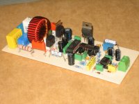
GOOD WORK and nice coil, how much turn of winding coil ?Here's my D200v2 build, it still needs a few parts to make it complete....
How long did it take you to complete the pcbHere's my D200v2 build, it still needs a few parts to make it complete....
PetruV,
DIY time will depend on your skill (experience) and on your approach (method) I have completed soldering all the pieces (mono) in 4hrs work,etching process (toner transfer) took me another 2hrs job, but I am dependent on the weather conditions,I do not have that temperature controlled etching tank... and by the way I also am a hobbyist, I'm no pro with electronics, so I guess skill will matter most in the process.
With regards to using wires, I do not have much experiences with vertical fets I used a temporary heatsink on my first class D build. My experience with wire tap on power outputs is with BJTs. Perhaps Sir Mile could confirm. I believe d200v2 pcb files for etching has already been posted somewhere in the pages, search back through the earlier posts.
Regards!
DIY time will depend on your skill (experience) and on your approach (method) I have completed soldering all the pieces (mono) in 4hrs work,etching process (toner transfer) took me another 2hrs job, but I am dependent on the weather conditions,I do not have that temperature controlled etching tank...
and by the way I also am a hobbyist, I'm no pro with electronics, so I guess skill will matter most in the process.With regards to using wires, I do not have much experiences with vertical fets I used a temporary heatsink on my first class D build. My experience with wire tap on power outputs is with BJTs. Perhaps Sir Mile could confirm. I believe d200v2 pcb files for etching has already been posted somewhere in the pages, search back through the earlier posts.
Regards!
pcb etching
regards,
freestyle
sir abetir, for pcb etching in any weather, i'm diluting with Clorox the ferric chloride for faster process.PetruV,
DIY time will depend on your skill (experience) and on your approach (method) I have completed soldering all the pieces (mono) in 4hrs work,etching process (toner transfer) took me another 2hrs job, but I am dependent on the weather conditions,I do not have that temperature controlled etching tank...
With regards to using wires, I do not have much experiences with vertical fets I used a temporary heatsink on my first class D build. My experience with wire tap on power outputs is with BJTs. Perhaps Sir Mile could confirm. I believe d200v2 pcb files for etching has already been posted somewhere in the pages, search back through the earlier posts.
Regards!
regards,
freestyle
Thanks for fast responseIf you have to ask, you cannot do it.
D
Deleted member 148505
How can you print a correct size pcb from an image file?
You need to know the size of the pcb first, crop the pcb image and paste it in MS Word, right click and select "size and position", then adjust the size accordingly.
After you print, check fit the IC in the image to make sure that you printed the correct size, because sometimes the printer's "margin" setting makes the image smaller.
Save it to PDF after you verify that you printed the correct size.
D
Deleted member 148505
im really building this at 90 v along with a smpsu
The amp is really designed for +-55V, make it work first at that voltage before trying higher rails.
You will just lose your precious mosfets and the driver IC if you stubbornly run it at 90V.
It might work at first but will blow up eventually because of reliability problems.
For 75V operation:
- zobel resistor will heat up, replace it with 5W and change cap to 100nf 250V
- change mosfet to irfb4227
- change gate resistor to 10r
- replace 4k7/2W resistors with 8.2k or 9.1k 2W
- remove current sense resistor, it will melt if you draw large currents, if you really need it, put 0.03R 15W, (OC protect will trigger at 20Amps), or redesign the OC protect circuit
- I really doubt if the voltage regulator will be reliable for continuous usage.
regulating voltage from 75V down to 12V will make the transistor very hot if you don't mount it in a very large heatsink. No current limiting resistor too.
So a better option is to replace onboard transistor regulator with external bias supply (LM350 and 16VDC 2A supply, regulated to 12V)
- level shifter is good, i think it will work at 75V
- retain value of osc freq resistor, switching freq will go up if you put a higher value resistor, you really need a scope here to see the switching freq.
- (optional) to slow down RC time constant for VB charging, cut the trace between 47uf VB cap and mosfet's VS track, then connect them with 1 ohm 1W resistor
- (optional) change feedback to 82k
- (optional) use IRS2110 instead of IR2110, for better reliability
- (optional) find NAND/NOR/NOT gate IC with 15V supply with good specs so that 5V regulator won't be needed (needs layout to be redesigned)
Regards,
Lester
Last edited by a moderator:
D
Deleted member 148505
Here's my D200v2 build, it still needs a few parts to make it complete....
Superb craftsmanship
(optional) use IRS2110 instead of IR2110, for better reliability
try FAN 7392
Hi andrew,
i think IR and FAN little different ; Logic side of IR is respect to -ve rail and FAN is GND
so you can't use or you modify your circuit
Regards
MANOJ
FAN7392 is superbly pin compatible with IR(S)2110, i use FAN7392 and its working brilliantly.
IR2110 has a Vdd/Vcc level shifter and FAN7392 has a Vss/COM level shifter internally, so technically we do not need those level shifter transistors we use in our class d projects.
IR2110 has a Vdd/Vcc level shifter and FAN7392 has a Vss/COM level shifter internally, so technically we do not need those level shifter transistors we use in our class d projects.
Thanks dudes youre the best,about the pcb i still need dimesions ,and im going to probaly if i find a cheaper ones,other mosfets,I seen people do this at 80v and the reg didnt give a thing,so 10 more volts would hurt it
Thanks again for your help,have a good day and wish me luck
Thanks again for your help,have a good day and wish me luck
- Home
- Amplifiers
- Class D
- Class D Amp with LM566, LM393 and 2XIRF530