Hi everybody,
this is my first message to the forum, this is a really vital area for newbies like me.
my problem that I need your help is about class d")
I designed a power amplifier for driving an underwater transducer, because the linearity is important I preferred class AB topology but as you know it heats so much and need bigger heatsinks so in the end that starts to be a mechanical problem (not enough space for the heatsink). I decided to use a class D amplifier. but I'm a starter for switching amplifiers. my design will be a little bit different from audio amplifiers (I'll work between 10khz-100khz) especially choosing gate driver is a big problem for me because as far as I know how fast (high frequency) I modulate the input signal I get better THD results (first of all Am I wrong?). I searched for high switching frequency fet driver (more than 4MHz) but I couldnt find a reliable one and decided to ask forum if anybody have a suggestion about this?
also If anybody has or know a document-application note etc.. about "class d amplifiers and underwater transducer applications", because people worked on transducer knows, it is an interesting load and usually you need to modify classical designs.
another question in a design like this, is it possible to use feedback to improve linearity, being realistic as a beginner do you think I can design a class d amplifier with feedback. and if you have a application note or document about feedback design please dont hesitate to give the links
thanks
this is my first message to the forum, this is a really vital area for newbies like me.
my problem that I need your help is about class d
I designed a power amplifier for driving an underwater transducer, because the linearity is important I preferred class AB topology but as you know it heats so much and need bigger heatsinks so in the end that starts to be a mechanical problem (not enough space for the heatsink). I decided to use a class D amplifier. but I'm a starter for switching amplifiers. my design will be a little bit different from audio amplifiers (I'll work between 10khz-100khz) especially choosing gate driver is a big problem for me because as far as I know how fast (high frequency) I modulate the input signal I get better THD results (first of all Am I wrong?). I searched for high switching frequency fet driver (more than 4MHz) but I couldnt find a reliable one and decided to ask forum if anybody have a suggestion about this?
also If anybody has or know a document-application note etc.. about "class d amplifiers and underwater transducer applications", because people worked on transducer knows, it is an interesting load and usually you need to modify classical designs.
another question
in a design like this, is it possible to use feedback to improve linearity, being realistic as a beginner do you think I can design a class d amplifier with feedback. and if you have a application note or document about feedback design please dont hesitate to give the linksthanks
Give us more data: power, transducer load, acceptable ripple, wheather you need full power at full bandwidth, etc.
Concerning switching frequency, the distortion actually increaes with frequency before applying feedback. The slope of distortion increase is around 6dB by octave, the feedback can reduce the overal distorion by 6 or more dB per an octave of frequency increase, depending on how fancy feedback scheme you want to use. So distortion to switching frequency dependacy is not vey straightforward and much topology dependant.
If I were in your shoes I'd go for around 1MHz switching frequency with standard "fast" mosfets and drivers.
This looks like a good place to start:- Amazon.com: Introduction to the Theory and Design of Sonar Transducers (9780932146229): Oscar Bryan Wilson: Books.
If I was building a sonar I'd get my employer to buy me this book.
w
If I was building a sonar I'd get my employer to buy me this book.
w
Give us more data: power, transducer load, acceptable ripple, wheather you need full power at full bandwidth, etc.
Concerning switching frequency, the distortion actually increaes with frequency before applying feedback. The slope of distortion increase is around 6dB by octave, the feedback can reduce the overal distorion by 6 or more dB per an octave of frequency increase, depending on how fancy feedback scheme you want to use. So distortion to switching frequency dependacy is not vey straightforward and much topology dependant.
If I were in your shoes I'd go for around 1MHz switching frequency with standard "fast" mosfets and drivers.
hi,
thanks for the answer.
I tried a simple LTSpice simulation to see if the THD increase or decrease with increasing modulation frequency. the result shows as modulation frequency increases THD decrease. I used pulse wave genarators to drive mosfets in the simulation may be this creates difference.
and specs of the design are like this:
-2 channel X 25W
-0.01 THD
-better than %90 efficiency
-full bridge topology
-the power changes through the bandwidth because transducer has a piezoelectric characteristics so it doesnt need full load at every time thorugh the band.
you suggest t start with standart fets and drivers. what about the feedback issue is it possible to use feedback with full bridge or is it needed?
thanks again also any documents and notes is more than appreciated.
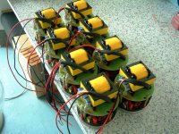
oh!we have some type of amp for sonar ,it can works well at 3KHz-30Khz,we are now develop new type for 100Khz series,our sonar amp have used in military project,of course some more problems need to resolve,like deminsions and stablity,100W /300W/500W with transformer have produced,out voltage about 200-600V,we suggest it works at narrow band mode,if you use full range signal the output will undulations.
Attachments
Within your specs you forgot one important value: The load impedance.
If those whimpy 25 watts had to be delivered into 8 Ohms for instance you could use fast and beefy MOSFET drivers (like some types from IXYS) for your output bridge. If OTOH you need 100 V RMS in order to achieve 25 Watts things don't look that nice anymore.
Regards
Charles
If those whimpy 25 watts had to be delivered into 8 Ohms for instance you could use fast and beefy MOSFET drivers (like some types from IXYS) for your output bridge. If OTOH you need 100 V RMS in order to achieve 25 Watts things don't look that nice anymore.
Regards
Charles
oh!we have some type of amp for sonar ,it can works well at 3KHz-30Khz,we are now develop new type for 100Khz series,our sonar amp have used in military project,of course some more problems need to resolve,like deminsions and stablity,100W /300W/500W with transformer have produced,out voltage about 200-600V,we suggest it works at narrow band mode,if you use full range signal the output will undulations.
Make clear,one underwatertransducer impedance characters curve necessary indeed.
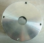
underwater transducer
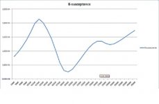
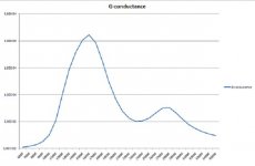
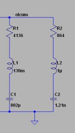
as you know piezo transducers have a admitance (impedance) changing through a frequency band, I uploaded the susceptance vs frequency and conductance vs frequency graphs to make load characteristics of the power amplifier clear. I extract a lumped model of the transducer to use in simulations (also uploaded it.) I'll drive the load by using a transformer (I need high voltage as you see from the lumped model transducer have big impedance).
to phase accurate: I use transformer after the amplifier to get high voltage levels.
to authlxl: the project you worked on I think merely the same if you share your experiences and if you have vital documents about this design I'll be so glad.
thanks everybody for your interest. I hope I made it more clear.
Attachments
Make clear,one underwatertransducer impedance characters curve necessary indeed.
one type underwatertransducer impedance characters curve:
Attachments
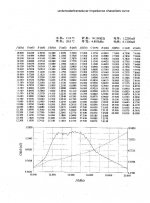
is there a problem with the uploaded files? I cant understand. I now uploaded the txt file for the conductance and susceptance values vs frequency. this shows my transducer's characteristic.one type underwatertransducer impedance characters curve:
Attachments
hi,
thanks for the answer.
I tried a simple LTSpice simulation to see if the THD increase or decrease with increasing modulation frequency. the result shows as modulation frequency increases THD decrease. I used pulse wave genarators to drive mosfets in the simulation may be this creates difference.
and specs of the design are like this:
-2 channel X 25W
-0.01 THD
-better than %90 efficiency
-full bridge topology
-the power changes through the bandwidth because transducer has a piezoelectric characteristics so it doesnt need full load at every time thorugh the band.
you suggest t start with standart fets and drivers. what about the feedback issue is it possible to use feedback with full bridge or is it needed?
thanks again also any documents and notes is more than appreciated.
For the constant timing error of switching waveform (due to dead time, jitter, propagation delay vriations etc.), the distortion goes up with frequency, because the timing error becomes larger and larger fraction of the switching period. 20ns of timing error is 'no distortion' at 10us period and 'a lot of distortion' at 250ns period. As simple as that, take it for granted
If you start, go for fast low voltage driver like UCC27200 or LM5101 and fast switching mosfets rated maximum Vbrds at 55 to 60V, like IRFI4024H-117P (dual) or IRFZ44Z (single, more powerful). Select the transformer to match voltages and power.
Wheather you can end up with <0.01% THD at 25W at 100kHz at 90% efficiency is questionable, this is a bit cutting-edge for todays class-D technology. The transformer design itself can be challenging here.
If you can do it, you are the man indeed.
If your efficiency and distortion requirements aren't a bit negotiable, it may actually turn out simpler to build class-G or some other sort of economic linear-mode amplifier.
Regards,
Adam
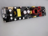
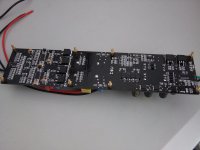
wide band high voltage underwater sonar class D amp
Power supply: 18-30v 10A dc seawater cell or other battery
Signal input: 1Vrms differencial signal.
Frequency Respon: 20Hz~50Khz +/-1dB
Amp type:class D,
Center Frequency:680Khz-800Khz
Output: 90-130V rms (Btl out)
Efficiency: 80% full load
oh!we have some type of amp for sonar ,it can works well at 3KHz-30Khz,we are now develop new type for 100Khz series,our sonar amp have used in military project,of course some more problems need to resolve,like deminsions and stablity,100W /300W/500W with transformer have produced,out voltage about 200-600V,we suggest it works at narrow band mode,if you use full range signal the output will undulations.
Power supply: 18-30v 10A dc seawater cell or other battery
Signal input: 1Vrms differencial signal.
Frequency Respon: 20Hz~50Khz +/-1dB
Amp type:class D,
Center Frequency:680Khz-800Khz
Output: 90-130V rms (Btl out)
Efficiency: 80% full load
Attachments
Power supply: 18-30v 10A dc seawater cell or other battery
Signal input: 1Vrms differencial signal.
Frequency Respon: 20Hz~50Khz +/-1dB
Amp type:class D,
Center Frequency:680Khz-800Khz
Output: 90-130V rms (Btl out)
Efficiency: 80% full load
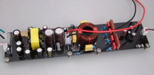
I like it. Can you post a schematics ? If not, can you tell what topology you use, like self-oscillating, triangle, etc. ?
Also what IC you use for the "brains", what MOSFETs, etc. ?
- Status
- This old topic is closed. If you want to reopen this topic, contact a moderator using the "Report Post" button.
- Home
- Amplifiers
- Class D
- class d for underwater transducer