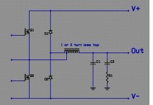
Here an elegant way to bypass body diode. Just put a tap 1-2 turn before the mosfet node to bypass the Vf of the body diode, ie to get more than the conduction of the internal body diode. In that way external diode conduct way before the slow body diode and all recovery current flow trought the external diode! I have made a prototype with slow APT5010LVR mosfet and IXYS DEE30-12A at +/-250V. Have only done test with 50% duty cycle, but with load swapped to V+ and V- to see worst case load. I got about 15A flowing in the external diode and less than 0.8A in the body diode. I was using a 15 Ohms 1000W load durring test.
Attachments
 What will happen if the load is lower ohm, like 2 or 4 ohm?
Should not be a problem...1 Step at the time! I only have 15 Ohms high power resitor to take my time to make measurement.. But even with my 15 Ohms, it's about 3600W feed to them when swapped to V+ or V-! I do test for about 2-3 minutes before I smell my resistor! Tomorow I will drop supply to +/-100V to do test with 4-8 ohms load. My output are rated at 50A, but I will have to limit current to 35A due to IXYS diode. That's just a proto to validate my assumption..
Total in my case 27 turn, 1 turn to external diode. I wrote 1-2 turn for anybody that not using same material as me, to try and test! at 250V, I got about 9V difference more that is (lot!) enought to force recovery energy to external diode, at expense of some heating in that turn, so I use 10 gauge litz wire for this one and 12 gauge for the remaining 26 turn. External diode heat a bit, but nothing to worry! So depend on supply voltage, 1, 2 or maybe 3 turn more will be required. Overall, in my case, I got better circuit effiency than any other combination at this voltage.
Hi Fredos
I have some doubts about that circuit, let's go back to basics.
Normally during one PWM cycle mosfets force full rail to rail voltage swing, what you have done is you've added one (or two) extra windings in series so that you've created a boosting autotransformer. This way the midpoint of diodes is 'trying' to get the voltage swing above rails, but the diodes clamp it back into rails. Smells like short circuit to me, sorry for that. I guess you may expect some extra current in both the mosfets and diodes during the whole cycle, not only in the dead time body diode conduction period.
This way you might have increased conduction and switching losses a lot.
Keep extinguisher handy if I am right.
Regards,
Adam
I lost some watts at idle, but got lot better effiency at (equivalent) 0% and 100% modulation, when load is connected to +/- Rail. I know that I short 1 turn to rail (less diode drop), but this seem to force freewhelling current trough the diode and not the body diode. A major advantage at high power. I drop supply to +/- 60V ( 2 turn tap) today and place a modulator (open loop) to check at different duty cycle. It seem that at all duty cycle, less than 5% of freewhelling and recovery current pass trought body diode. More I got close to 0% and 100%, less idle power is lost in the external diode. At idle (50%) I got about 1A flowing trough diode, nothing stressing, about 0.6W of loss (50% duty cycle). When I reach 30A of load current, I got about 15.5A flowing trough external diode (20W dissipation), nothing stressing too. Still have less than 1A trough body diode at all modulation. It's hard to compare with and without this trick, since body diode in the APT5010 are very slow ( 250ns at 25 celcius and 500ns at 100 celcius!). For sure at idle it's worst than any 200V mosfet, but at high volatge and high current it seem very better.
Wave are clean with no overshoot or rigging ( with snubber of course!), turn off behavior of both diode and mosfet seem good to me..
Wave are clean with no overshoot or rigging ( with snubber of course!), turn off behavior of both diode and mosfet seem good to me..
By the way: has anyone tried to store the energy of switching-on event and body diode conduction and recuprate it afterwards?
Recently I came across the so-called "flyback reset ZCS lossless snubber" or something like that, which introduces a one-way inductor to soften the switch-on/body diode conduction period and in the other direction recuperates the energy back into rails in a flyback style.
Any experiences, ideas, thoughts??
Adam
When I tried it in 1988 I also had the impression that it causes a short-circuit (FETs got very hot) but the switching signal looked impressively clean OTHO - although the circuit was built on breadboard.
The Peavey circuit uses a series resistor. I assume it is there to reduce the circulating current.
Regards
Charles
The Peavey circuit uses a series resistor. I assume it is there to reduce the circulating current.
Regards
Charles
Last edited:
You'll want that to be something like 1 turn out of 50 (depends on supply voltage, essentially Vf(diode) / Vsupply), which may be a steep ratio for most coils that don't need that much inductance. Too low a ratio and it doesn't do jack; too high and you short out some fraction of the transistors' saturation region.
Personally, I'd rather shunt the MOSFETs with good diodes. A purpose-made silicon junction diode has lower voltage drop and much greater speed than a MOSFET body diode, so it turns on sooner, carries more current, and both together recover faster as a result. Schottky is also acceptable at *most* audio voltages. ("Super schottkies" are available up to 300V, though they have voltage drops comparable to, or greater than, junction diodes, the advantage being zero recovery and thus higher speed. SiC schottkies have significantly greater voltage drop and internal resistance, and are only useful in high voltage, very high frequency switching applications where recovery cannot be tolerated.)
If you use a core with multiple return paths (E types, or even those four prong things if you can ever find them), you can use a flux unbalancing winding to allow fractional turns around a single limb. The method acts like a vernier on the windings.
Example: suppose you have 10 turns on a core to achieve the correct inductance. Obviously you can't make a 1/50th ratio the normal way. If you loop a separate winding around the two limbs, one turn each, so that the flux in each must be equal, then you can make half-turn windings successfully. But 1/2 out of 10 is only 1:20, and we need 1:50 in this example, so we need 1/5th of a turn. You can wind 4 turns on one limb and 1 turn on the other, to enforce a 4:1 split (1/5 and 4/5 of the total), but this reduces the A_e of the core by almost half (40% -- the 1-turn leg saturates much more easily). If you do a 2:3 split, A_e only drops by 20% (probably within design allowance). Now, if you pass a turn in the positive direction around the "3" leg and negative around the "2" leg, you get (3-2) / (3+2) = 1/5th of a turn, which can be connected in series with the main winding for a 10:0.2 ratio.
This is presented in more detail in an old Unitrode appnote, including winding techniques to minimize leakage inductance.
Tim
Last edited:
- Status
- This old topic is closed. If you want to reopen this topic, contact a moderator using the "Report Post" button.
- Home
- Amplifiers
- Class D
- Body diode bypass, elegant way!