Today in lack of anything to do i decided to revisit a cheapo class d topology that i've seen in manuals for flat screen tv's and such.
This is the circuit:

I call it the "Cheapo s**t class d"
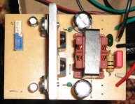
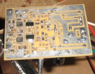
Since i dident intend this as a project, i dident put down much time in layouting, so heres a video of what i ended up with:
YouTube - Simple quick and dirty class d amplifier
Its running at around 600kHz, but started out at over 1MHz so i had to slow it down a bit. The fets are IRF9540 and IRF540.
Sound ? Pretty darn good for such a lashup, the low frequency response is wicked, it goes right down to DC!!!
In which thread was the similar circuits posted ? I can't remember.
This is the circuit:
I call it the "Cheapo s**t class d"
Since i dident intend this as a project, i dident put down much time in layouting, so heres a video of what i ended up with:
YouTube - Simple quick and dirty class d amplifier
Its running at around 600kHz, but started out at over 1MHz so i had to slow it down a bit. The fets are IRF9540 and IRF540.
Sound ? Pretty darn good for such a lashup, the low frequency response is wicked, it goes right down to DC!!!
In which thread was the similar circuits posted ? I can't remember.
Not quite, with a LM311 you cant get below around 0.1% THD due to its internal construction.
Above 400kHz is really just a waste of switching instants, since 300-400kHz is fully enough to produce a 0.01% THD or better full range class d amplifier.
Also, the P channel fet class d is not a good design, it was simply used because high side gate drivers dident exist back then and noone had yet figured out how to drive a high side N channel fet.
Why this kinda circuit is still in use in commercial products is that it dramatically reduces production costs.
Just wanted to remind you that the IR2110 already existed more than 20 years ago ! The current versions have better specs though.
Because I didn't like how it behaved back then I did an amp with complementary output stage as well. It had a DC path parallel to the capaciator coupling. And it wasn't self osciallating. The schematic can be found somewhere on this forum.
Regards
Charles
Because I didn't like how it behaved back then I did an amp with complementary output stage as well. It had a DC path parallel to the capaciator coupling. And it wasn't self osciallating. The schematic can be found somewhere on this forum.
Regards
Charles
It works better from the same rail, low voltage only. That way you don't have to worry about Vgs(max) or DC restoration hacks (as shown).
For most MOSFETs, you need shorting-mode commutation, because Vgs(th) is small and shoot-through occurs when both transistors are switching.
My block-model class D amp seems to be working fairly well, by the way. "Complementary" H bridge output.
Tim
For most MOSFETs, you need shorting-mode commutation, because Vgs(th) is small and shoot-through occurs when both transistors are switching.
My block-model class D amp seems to be working fairly well, by the way. "Complementary" H bridge output.
Tim
I have been messing around with it some more and eventually damaged something which caused the amp to temporarily stick to one of the rails above a certain volume, so i decided to short the speaker terminals and see what would happen, volume on max and heavy clipping and rail sticking, whilest still on a heatsink it just kept on going, got hot but nothing else.
I've never before had an amplifier survive full volume into a dead short!
I've never before had an amplifier survive full volume into a dead short!
I'm not saying that it's a bad topology, I like it, it can be reliable and effective but only with a careful implementation (paralleling the right combination of supply rail decoupling caps, using the right snubbers, etc.) The rails must not bounce after switching because they are in series with gate drive.
The main advantage is the low propagation delay because the floating gate driver is avoided, which opens the door to ultra-low 0.00x% THD in self oscillating modulators.
The main advantage is the low propagation delay because the floating gate driver is avoided, which opens the door to ultra-low 0.00x% THD in self oscillating modulators.
Last edited:
Or again, for low voltages, you can add a series inductor to the supply to allow for commutation.
Only if you want to loose control over the MOSFETs (and degrade the performance this way).
When your MOSFETs shunt 20A+ short circuit, bypass isn't necessarily a good thing!
Here the bypass is a must, because the supply voltage is one part of the control voltage. If you want to avoid cross-conduction, you have to provide the neccessary amount of dead time as usual.
Fets don't die unless they get too hot, atleast not yet.
Heres some brutal testing: more class d, new frontend TheElectronoob on USTREAM. Other Technology
Heres some brutal testing: more class d, new frontend TheElectronoob on USTREAM. Other Technology
So you prefer to destroy transistors instead? How does that work?
Not connecting the gates together. The simplest approach is capacitive coupling of the gates, with clamping diodes and zeners to get the coupling capacitors charged with the right voltage. Then, the next improvement is a parallel DC gate drive path (slower) to allow it to operate at any frequency.
Aight i just finished a brutal destructive test on this thing, for over 2 hours i ran it with 35v rails into heavy clipping and on lower level signals.
The fets and heatsink got HOT but it just wouldent die, after over 2 hours of trying, i decided to try shorting the output, then finally it let go of the magic smoke.
So its a pretty reliable amplifier despite not beeing very efficient. On normal listening levels it gets about as hot as a class A amplifier.
- Status
- This old topic is closed. If you want to reopen this topic, contact a moderator using the "Report Post" button.
- Home
- Amplifiers
- Class D
- P channel class d anyone ?