Hi,
I see no defects, this is exactly Tripath (TAO105A) very clean output ...
Regards
I see instability as the output approaches the rails. That's usually a design problem, something you can't just fix without an improved PCB and changes in the circuit and the type of components used. You are in no way required to fix that.
The customer paid a lot of money for the instability when the amplifier was bought, why removing that "feature"?

Thanks, Eva for your clear explanations.
I'm thinking now "my" amplifier is running "normally".
I said "normally" because I'm no used to see so ugly forms coming from the high end make Audio Research. They' ve built the best world's preamplifier with their fantastic SP15witch inspire respect. I never though to see a such result coming from them, and it's why I believed there were many faults in the boards.
But at this time, everybody wants little loudspeakers with the sound of the big ones, and needs extra-powered systems. I say it's a very bad idea, a contrebass sound will never go out of a cello. Take big Altec or JBL or BW loudspeakers and you'll do the work with a 5 watts or 500 amplifier with your choice of Class. You'll be rarely disappointed.
The owner of the AR had before the big big Onkyo M-510 and told me the result was much better with it. He regrets it so much now......
I've invited him to resell the AR and try the super tube amplifier Mega Baron ! I heard it and it's amazing ! A world of difference...
But tubes (and output transformers) are good distortion generators too...
Try feding 30Khz (or 30Hz) to a high end tube amplifier and looking at the output with oscilloscope
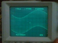
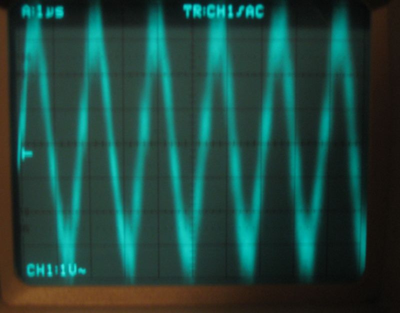
These pictures show how a clean class D output should look at increasing amplitudes. Operating frequency is only 120khz since the amplifier is primarily intended for bass and sub-bass. Test frequency is 2khz.
Pic 1: 1V/div
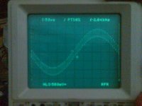
Pic 2: 5V/div
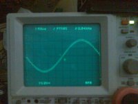
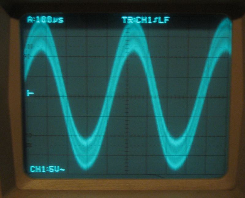
Pic 3: 20V/div
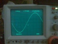
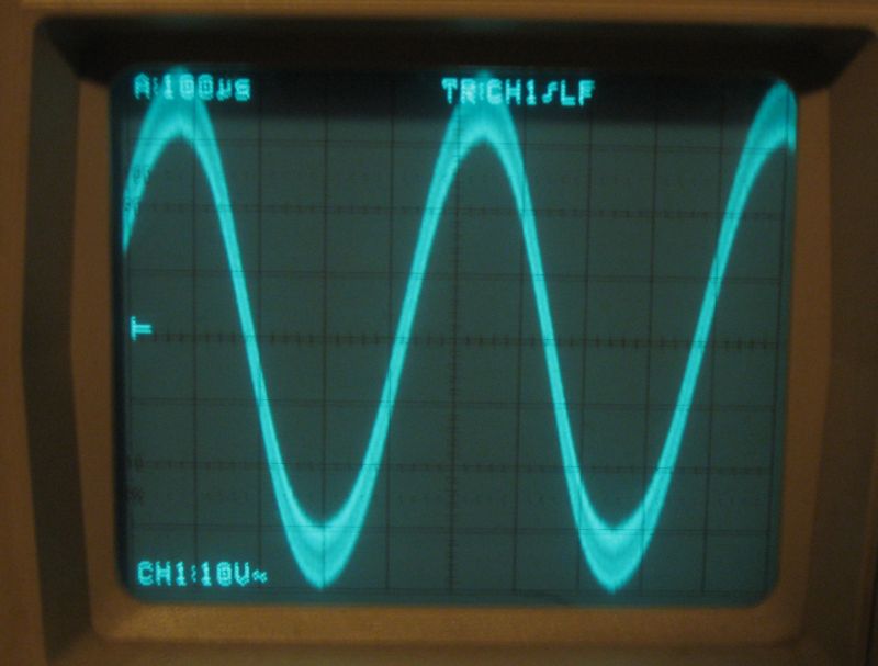
Pic 4: 50V/div (the amplifier is quite powerful).
Note how the amplitude and shape of the carrier residual remains more or less constant and the audio signal appears just added, moving residual waveform up and down.
Try feding 30Khz (or 30Hz) to a high end tube amplifier and looking at the output with oscilloscope
These pictures show how a clean class D output should look at increasing amplitudes. Operating frequency is only 120khz since the amplifier is primarily intended for bass and sub-bass. Test frequency is 2khz.
Pic 1: 1V/div
Pic 2: 5V/div
Pic 3: 20V/div
Pic 4: 50V/div (the amplifier is quite powerful).
Note how the amplitude and shape of the carrier residual remains more or less constant and the audio signal appears just added, moving residual waveform up and down.
Attachments
Last edited:
The tube amps are a class of its own right, are devices that allow music reproduction otherwise dynamic, yet softer, warmer, less nervous and less muddled than their opponents transistor, Mosfet well equipped. Transistor can exceed the tubes only as measures, never listening.
- tubes are working at a voltage much higher than the transistors; filtering capabilities have less power to be restored at a power demand, the response is faster and therefore you gain the transparency and vividness .
- tubes generate very little harmonics 3, those who attack the most ear.
- the movement of electrons is seven times faster in the vacuum than in the field
- tubes are no-sensitive to temperature changes and are obviously more stable than the transistors that have their characteristics changed with temperature and the necessity to design compensation circuits which complicate the pattern
- tubes amplifiers never send dc voltage witch burn loudspeakers
- clipping is softer and less dangerous for the (expensive) speakers on tubes amplifiers
- tubes amplifiers are electrically more robust, not shockproof but it's not the target.
These are Pic 3 and Pic 4.
Edit: I forgot clipping so one more picture was added (the amplifier has built in limiter but I disabled it to take the picture). The picture was taken without a load, the hardest condition for class D, but it looks damped as if a load was used. There is no output zobel either, only clamps to the rails. Many amplifiers will produce far worse waveforms.
You missed one feature of tube amplifiers:
- Someone making his life on selling and repairing them for a long time will hardly admit that there is something wrong with them.
Attachments
Last edited:
Yes, it's a full bridge with 170V typ. and 200V max. supply voltage, and it's capable of 80A peak. Try to do that with tubes I do it with eight TO-220 output devices in less than 4kg. This amplifier is being used in big powered bass systems for big live music performances.
Note that I added another picture.
I do it with eight TO-220 output devices in less than 4kg. This amplifier is being used in big powered bass systems for big live music performances.Note that I added another picture.
Last edited:
I' ve more residual carrier. I suppose Fc of the filter cuts higher ? What's the value of the rc components ?
But in the 4th picture, 50 volts / div, you're sure ? 300 Volts PP ?
The output filter of your amplifier is not designed properly. The wrong type of coil, the wrong resonant frequency... Once again, the customer paid extra money for these "features" so there is no reason for you to fix them.
A contract prevents me from revealing component values, but the resonant frequency of my filter is quite low, around 12khz (with useful flat clean output up to 10khz, thanks to the type of control loop used, superior to "class T"), while I think the Fr of your filter is higher than needed. The air coils are probably too low inductance (PCB copper, the case or anything conductive, close and placed in the winding plane, can act as a shorted turn), and I think output capacitors are too low on value too.
Last edited:
It's a llow-pass filter, more high is the fc, more effective is the attenuation in audio spectrum, isn't it ?your filter is higher than needed
If I double the capacitor, the residual carrier lower to half of it was.
I'll try this evening to post pictures in same conditions as yours, now I'm going to take off the front springs of the spider, and I must take care, otherwise I'll loose some body parts here and there :>)
For a low-pass it's the opposite, a higher resonant frequency results in less attenuation for any frequency above resonance.
Suggested filter (optimized for 8 ohm tweeter with 20 to 200uH inductance): 22uH / 470nF LC low-pass and then 22ohm and 680nF RC damper. 500khz attenuation is approx. 40dB. Resonance happens around 45Khz.
Suggested filter (optimized for 8 ohm tweeter with 20 to 200uH inductance): 22uH / 470nF LC low-pass and then 22ohm and 680nF RC damper. 500khz attenuation is approx. 40dB. Resonance happens around 45Khz.
I see instability as the output approaches the rails. That's usually a design problem, something you can't just fix without an improved PCB and changes in the circuit and the type of components used. You are in no way required to fix that.
The customer paid a lot of money for the instability when the amplifier was bought, why removing that "feature"?
Hi EVA...I said sarcastically, is clare that amplifier (this) is absourd...completely out of D class audio amp. (story of this chip is very long on tripath) I...know.
Ok, Your photo are clean, whay not show Vcc rail on ch2 ? this ref is necessary for understand.
Regards
The capacitance of the AR is 0.22 uF. I didn't measure the self. But as you say, I've not to fix it, but It could be upgraded rather easily. Have you seen on the pictures all the little capacitors wired to the speakers terminals ?
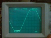
Here are some pictures, 2.000 Hz, no load, 2 V/div : the signal is lost into residual carrier
Same, 5 V/div
Same, 10 V/div
Same, 20 V/div
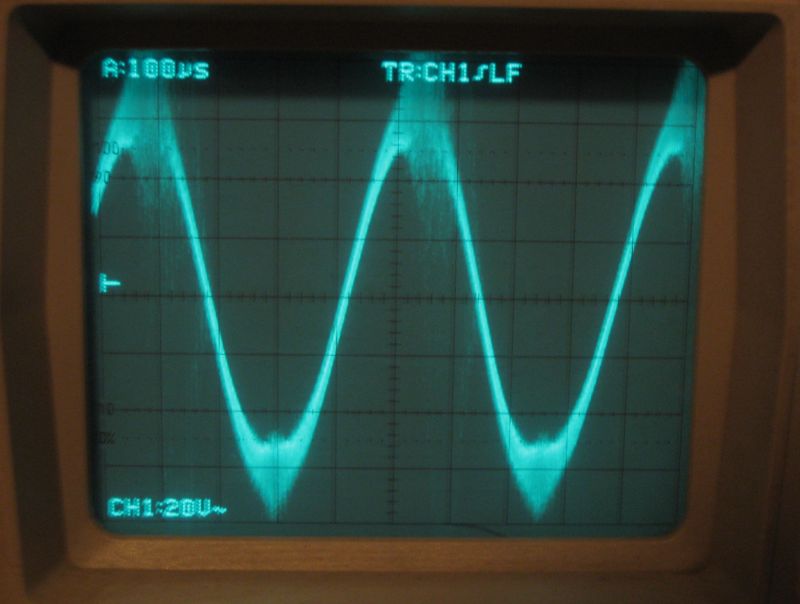
You could replace the AR' engineers !
Sometimes, I upgrade high end amplifiers for fortunated customers, and no-fortunated friends. Inbelievable faults that occur top amplifiers.....
P.S. : Have you ever seen a 10 KHz square signal on a tube preamplifier AR SP-15 ?
Here are some pictures, 2.000 Hz, no load, 2 V/div : the signal is lost into residual carrier
Same, 5 V/div
Same, 10 V/div
Same, 20 V/div
You could replace the AR' engineers !
Sometimes, I upgrade high end amplifiers for fortunated customers, and no-fortunated friends. Inbelievable faults that occur top amplifiers.....
P.S. : Have you ever seen a 10 KHz square signal on a tube preamplifier AR SP-15 ?
Last edited:
Hi,
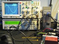
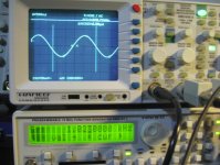
I do not want to compete with the EVA. but I can show what my concept of class D amplifier
This is a new very compact proto 500W out. simple ... not Have Intermodulation from carriers. Sound is as class AB. (This is a normal commercial amplifier not esoteric for me).
To EVA:
I have no doubt that you did a good job. you should try to do something very fast signals with 400kHz and to see if what you have gained can be applied ...
+/-60V Rail ,amplifier loss 500mV from rail...completely clean.
Carrier 500mV/Div Power Out 20V/Div
Regards
Attachments
Last edited:
Not delete, not have (very low), filter is 10uH with 680nF only. this is not selfoscillant amplifier.When I see that I'm wondering if AR engineers are the same than in the past !
What you done to delete the carrier ?
If you see thd vs. power, it is very similar as AB class (low up to 95%-97% of power)
Last edited:
The AR amp is tripath based which is also a clocked non self oscillating design.
The weird behaviour is likely caused by the air cored output inductors combined with a class AB like board layout, along with those large axial audiophile capacitors.
They dident even look at the reference design in the datasheet.
The weird behaviour is likely caused by the air cored output inductors combined with a class AB like board layout, along with those large axial audiophile capacitors.
They dident even look at the reference design in the datasheet.
When I see that I'm wondering if AR engineers are the same than in the past !
What you done to delete the carrier ?
Self oscillating amplifiers try to keep carrier residual amplitude constant, resulting in a progressive drop in oscillation frequency as the output approaches the rails. This improves efficiency as the amount of switching events is reduced. My pictures show this behaviour.
Clocked amplifiers keep oscillation frequency constant, and carrier residual amplitude tends to 0 as the output approaches the rails. AP2 pictures show this behavior.
So carrier residual appears smaller on clocked amplifiers, while in self oscillating it becomes more and more evident due to the drop in frequency as the output approaches the rails.
Furthermore, there is one design trend towards as low carrier residual as possible, often compromising performance, and another trend towards accepting carrier residual as something harmless and allowing as much as required to optimize other circuit aspects. I follow the latter.
But till it seem like the UcD type class d is considered to have the most pleasing sound.
Bruno's approach was to keep the self oscillating topology, yet minimizing the frequency drop by using the output filter to create a phase shift oscillator, supposedly reducing the change in frequency.
Im guessing this is why fumac drove up the switching to 1MHz, to compensate for the frequency drop in the hysteresis pre filter feedback type class d he uses and still keep a reasonable efficiency, rather than redesigning it to a phase shift oscillator design like UcD.
Last edited:
Hi,
TO EVA.
I agree except that the loss per cycle because it is negligible.
the work that I did not for the residual but to turn the modulator completely linear up to 98.5%, pic shows this result also.
residual is not very important, but the intermodulation (inherent in selfoscillator). this , especially mids (voice etc) create multiple on audio band and is not good for very good amp.
I'm sorry to destroy castles created around selfoscillators amp, but this is a reality.(measurable reality)
Last edited:
This is the measurable reality:
plot 1 : 2khz + 3khz 1:1 intermodulation test at -6dB from clipping into 2 ohm (>150Vpp)
plot 2 : same test at -1dB from clipping into 2 ohm (>260Vpp)
plot 3 : same test in loopback mode, skipping only the amplifier (and output attenuator) and keeping the 20khz brickwall filter used to remove carrier residual
Don't trust the IMD figures calculated by the program, they are being disturbed by 50hz mains induced harmonics in plot 1 and plot 2. Compare the second and third order intermodulation products instead (if you happen to know what they are).
Note that this is a 120khz subwoofer amplifier with 10khz bandwidth so the test is really demanding, yet I'm sure it performs better than your hi-fi clocked modulator.
btw: Frequency drop cuts switching losses by approx. 50%. and total losses by approx. 30%.
Don't be like the AR class-D fools, you can do better than that.
Step 1: Delete all myths from your brain.
Myth #1 to delete: "Phase-shift self-oscillating amplifiers produce high IMD."
Attachments
Last edited:
- Status
- This old topic is closed. If you want to reopen this topic, contact a moderator using the "Report Post" button.
- Home
- Amplifiers
- Class D
- Faulty amplifier