Once that was working, I couldn't resist trying to match the waveform photos Eva posted. This required some intelligent guessing of the form of her secret di/dt control circuit. Attached are waveforms for moderate output power with and without added dead time. What do you think? Is it a good match?
For dead time induced distortion analysis I think your model is very accurate, it contains the most important elements. There are several more elements in the real circuit, but they don't have a direct impact on dead time, they just improve switching performance.
I think I gave enough hints for someone like you to guess the di/dt limiter implementation. But if you do it, please don't publish, otherwise everybody would start copying it without a clue about how it works.
For higher current waveforms see post 15. Note that these waveforms are all obtained from MOSFET pairs wired in parallel. The parasitics in a single device are not the same, but can be calculated.
There are several more elements in the real circuit, but they don't have a direct impact on dead time, they just improve switching performance.
I simplified Q killers and left out certain snubbers in the interests of a smaller schematic. Also some of my own designs (power supplies and inverters) have had negative gate drive (the necessity for this depends on the voltage being switched and the ratio of the drain-gate capacitance to the gate-source capacitance in the MOSFET). Some circuit topologies benefit from dv/dt feedback to shape the gate drive.
I think I gave enough hints for someone like you to guess the di/dt limiter implementation. But if you do it, please don't publish, otherwise everybody would start copying it without a clue about how it works.
You probably noticed that I didn't include any of that in the schematic I attached for Baldin in another thread. I was thinking it wouldn't be nice to publish it without at least soliciting your comments first, so I will keep it to myself - at least for the time being. Anyway, there is a good chance my guess is something other than just what you have done - even though your di/dt circuit seems really simple and obvious to you, all it takes to add a few elements and the possible ways to achieve more or less the same results are often several and surprising.
One thing about the simulation that was satisfying (and impressive about LTspice) was how easy it was to display the results in triggered form in order to reproduce your scope "shadow" photos.
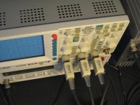
By the way, it wasn't entirely clear from your earlier posts exactly where and how you were measuring the gate drive signal. Was it directly on the MOSFET pins using a scope tip jack or equivalent (i.e., no ground lead with direct connection to the probe tip ground ring)? Or was it taken to the other side of the di/dt circuit, which might be common for several MOSFETs?
Also, was it using high quality probes matched to the scope? (Some of the cheap ones from China have bad peaks in the high end that don't show up in the calibration pulse adjustment, but they can badly distort gate drive measurements.)
Regards -- analogspiceman
You are right, there are both gate-source and drain-source snubbers on my circuit, and they are RC tuned with parasitic L. The di/dt limiter is probably as simple as you figured it out, it involves zeners, resistors, diodes and source parasitic inductance.
The waveforms are measured by directly connecting probe tip and ground ring very close to MOSFET leads. I don't think these probes suffer from any substantial peaking or notch at least up to 100Mhz, they are HAMEG branded and 10 year old.
The waveforms are measured by directly connecting probe tip and ground ring very close to MOSFET leads. I don't think these probes suffer from any substantial peaking or notch at least up to 100Mhz, they are HAMEG branded and 10 year old.
")
But if you do it, please don't publish, otherwise everybody would start copying it without a clue about how it works.
Don't bother. The fundamental 'ice age version' with some nH external inductance is being published and ignored since years.
It is not very likely to copy successfully your more cost effective version just from the schematic, but without understanding.
...well, and who understood the old 'ice age version' can do it on his own anyway.
Hi all,
first let me apologize to "authlxl" because this is his thread with different subject and we have deviated.
for what he said EVA agree only if the circuit has been developed and therefore the cost of development oriented to commercial product. where different ideas and think right Advertise Ad block diagram for the sake of the community. (My opinion is that the method you used is not innovative and not perfect) so you have to worry about.
to "chocoholic."
sorry if I have not replied to your post referring to the circuit (dynamic change DT) I'm developing.
yes, your explanation is very similar to reality. I believe it is right to create these signals control the first driver circuit and leave the work clean engine power. Moreover, in this case, the circuit can be controlled by other devices or other circumstances.
Best regards
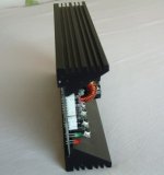
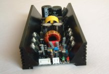
Extremely discuss end at last,newer irs2092 AMP finished,400W/4ohm/1%THD+N.
OTP/OCP/DCP/UVP function inside.220V or 110v ac supply,but EMI part is separated. 1u height.
IRS2092 have excellent performance,we suggest it can be widely applicated to mid power pro amp.simple circuit and high stablity.
OTP/OCP/DCP/UVP function inside.220V or 110v ac supply,but EMI part is separated. 1u height.
IRS2092 have excellent performance,we suggest it can be widely applicated to mid power pro amp.simple circuit and high stablity.
Attachments
Last edited:
We have test many times,Irfb4227 and 4229 will good performance in this topology.
the DT time can decrease 1/2 when in this circuit,I use irfb4227 at 600W board,dt set 75ns,the mosfet hot quickly,from normal to 90oc at rated power.but in this circuit,dt at 45 ns,same frequency,same condition,mosfet body tempreture only increase 20oc.
I suggest friends can discuss The diode choice .we use 40A ultrafast diode,
mosfet is irfb4227.
The 4227 has quite a large gate capacitance. I found my 2092 got quite hot with those. I got a much better performance with irfb4019, these have a lower gate capacitance yet will still pass upto 17 amps and the 2092 runs cold.
- Status
- This old topic is closed. If you want to reopen this topic, contact a moderator using the "Report Post" button.
- Home
- Amplifiers
- Class D
- The simple way to improve the IRS2092 amp performance