klausix!
PSU cannot show the current of the inductor, because it doesn't flow through the power supply! It's reactive current, what means it takes energy from PSU (actually from decoupling capacitors) but then gives back almost the all.
8 is the exact value (in ideal case), 2*pi is a false simplification.
The basic equation (self-induced voltage in a coil): ul=dil/dt*L, now ul is PVdd/2, so dil/dt=PVdd/l, the time of the change: delta_t=1/(2*fsw), so delta_il=PVdd/(4*L*fsw), but this is the total change from minus Ipeak to plus Ipeak, so Ipeak is half of this.
http://www.diyaudio.com/forums/class-d/146167-new-classd-project-starting-0-a-7.html
Watch this thread, you will find there some interesant coils,that I have used.
Watch this thread, you will find there some interesant coils,that I have used.
Have anyone tried with T106-2 (red colored iron powder core) ? It should be working fine.. just look at the attached example 300Khz @ 50-50v
My new experiment is an air core, used 8x30AWG wire bunch and 1 inch Diameter x 1 inch height. Only 42 turns to give 30uH.. Warm up like 40-50 or max 60 Celsius but no more even at working !
My new experiment is an air core, used 8x30AWG wire bunch and 1 inch Diameter x 1 inch height. Only 42 turns to give 30uH.. Warm up like 40-50 or max 60 Celsius but no more even at working !
Attachments
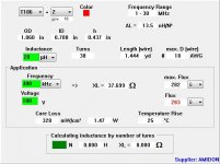
This is the most commonly used core for class d output filter inductors.
yes very true !
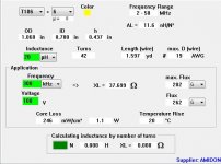
but the best is T106-6(yellow), just compare the above figures with this attachment..
The only problem is not very much available as red cores
")
Attachments
The only problem is not very much available as red cores
Not the only. More turns are needed, which means higher copper loss (and/or higher capacitance).
A good gapped ferrite has lower loss and needs less wire.
Can anybody tell me the calculation of wire gage of the output inductor (air core) for 600W amp under 2 ohms load and 50-50 voltage? Actually what i want to know is the current travel through the inductor then the gage can be calculated.. Just for experiments.. thanks in advance..
regards,
Lycanlk
regards,
Lycanlk
Can anybody tell me the calculation of wire gage of the output inductor (air core) for 600W amp under 2 ohms load and 50-50 voltage? Actually what i want to know is the current travel through the inductor then the gage can be calculated.. Just for experiments.. thanks in advance..
regards,
Lycanlk
The exact calculation (for optimal solution) is extremely complicated. (Especially without the design aims, desired inductance, etc...) I can say only one thing for sure: litz wire is needed. Inductor current is definitely not enough for calculating anything.
6 amps?
600 watts at 100v combined should be about 6 amps. No?
Can anybody tell me the calculation of wire gage of the output inductor (air core) for 600W amp under 2 ohms load and 50-50 voltage? Actually what i want to know is the current travel through the inductor then the gage can be calculated.. Just for experiments.. thanks in advance..
regards,
Lycanlk
600 watts at 100v combined should be about 6 amps. No?
600 watts at 100v combined should be about 6 amps. No?


Have you heard about ohm's law? 50V/2ohm=25 Apeak. But this is only the AF current, while there is the very important HF current, and the most tricky part: the eddy currents.
So it is advisable to spec the coils to handle a full on short of 2500 watts into 2 ohms in addition to the ultrasonic current in the filter?
I don't know where do you get these numbers from and what kind of handling do you mean.
What is your rough estimate of a safe current spec for his coils? 40 amps?
A coil can have thermal and saturation limit. An air-core coil cannot saturate. The thermal limit can have steady-state, or time limited, but you didn't specify any duration, so only the steady-state current limit left. The coil have to handle as much current as there can be flow. It depends on the designer and the purpose of the amplifier. Vdd/Rl=25A must be enough in any cases, but it's OK to use a 10 A capable coil in most cases.
The typical rms power involved in a music signal is around -10dB to -20dB with respect to peak power. This translates into 1/3th to 1/10th of rms current with respect to peak current. The ratio is higher for low frequencies, and lower for high frequencies.
In other words, a coil rated for 10A rms can usually handle 30A peak of audio in the worst case, and for example it would be suitable for a 1800W/4R amplifier (30A*4R=120V peak, and to produce those 120Vpk a 1800W amplifier would be required, (120^2/2)/4=1800, this is short term burst power, because long term power would be already limited to 400W by te coil, 10^2*4=400). 40A or more of saturation current would be required (30A peak plus 10A margin for ripple).
I hope the numeric examples help. There are simple methods to calculate optimum coils for audio.
Last edited:
For what it is worth, I recently had to design an inductor for a high frequency borderline discontinuous application (actually it goes to a controlled negative current value in order to force soft switching). The average current rating is 20 amps and the saturation level is 60+ amps or so. The operating frequency varies depending on load and line, but is typically around 200 kHz. The Q is well over 500 over the frequency range of 100 kHz to 300 kHz.
As could be expected, this required the use of a high frequency ferrite (gapped), but the most unusual aspect of the design is the configuration of the winding. With such high ac flux, proximity loss would easily dominate all other loss mechanisms with normal construction techniques, even with stranded wire.
The winding ended up being pseudo Litz wire (7 twisted bundles of stranded wire twisted - not as good as true woven Litz, but a lot easier and cheaper to make), but the real key was to space the winding away from the gap by 3 to 5 gap lengths and to separate adjacent turns within the winding by one wire diameter. This allows for evenly distributed current across the wire cross section so that losses don't rise much above what would be expected for skin effects for the stranded wire bundle.
The only practical core geometry that offers enough space to do this is a U-U (which is really much like a rectangular toroid). The gap is evenly distributed over both end faces of the U's and the two coil forms are very thick in order to space the windings away from each gap. Yes, there is some stray flux, so the the windings must not come within a few wire diameters of any conductive (i.e., metal) surface. This is the only way I have found to make such a high Q high frequency ac inductor (i.e., low inductance). A distributed gap ferrite core would be even better, but no such beast is commercially available as far as I know.
This sort of inductor construction technique is probably the only way to reach very high efficiency with class d, especially at idle, although that is usually not a very important design driver. Also, normal class d designs would tend not to need such a relatively low inductance, given all the rest of the inductor parameters being the same.
One advantage of a low inductance is that it pushes the class d output stage dual flat-spot distortion notches much further to either side of zero so that they only come into play at relatively high levels when absolute distortion doesn't matter as much anyway.
Regards -- analogspiceman
... The Q is well over 500 over the frequency range of 100 kHz to 300 kHz.
As could be expected, this required the use of a high frequency ferrite (gapped), but the most unusual aspect of the design is the configuration of the winding. With such high ac flux, proximity loss would easily dominate all other loss mechanisms with normal construction techniques, even with stranded wire.
The winding ended up being pseudo Litz wire (7 twisted bundles of stranded wire twisted - not as good as true woven Litz, but a lot easier and cheaper to make), but the real key was to space the winding away from the gap by 3 to 5 gap lengths and to separate adjacent turns within the winding by one wire diameter. This allows for evenly distributed current across the wire cross section so that losses don't rise much above what would be expected for skin effects for the stranded wire bundle.
The only practical core geometry that offers enough space to do this is a U-U (which is really much like a rectangular toroid). The gap is evenly distributed over both end faces of the U's and the two coil forms are very thick in order to space the windings away from each gap. Yes, there is some stray flux, so the the windings must not come within a few wire diameters of any conductive (i.e., metal) surface. This is the only way I have found to make such a high Q high frequency ac inductor (i.e., low inductance). A distributed gap ferrite core would be even better, but no such beast is commercially available as far as I know.
Regards -- analogspiceman
This is amazing! I did something similar, with E55 ferrites, stranded wire, 4 mm gap, I've left the space over the gap unwound, and it works perfectly in a 1.4 kW sub amp, the heat is almost unnoticable, but Q=500 sounds to be too good for me! Did you actually measure it? With max. power? What ferrite material did you use?
Last year I tried to make a high power inductor, I used N27 60 mm toroid cracked into 8 pieces, 8*1.8 mm gap, wound with 4*3*16*0.08 mm litz wire, (not too much, only 50 turns), and I got only Q=270 at 80 kHz.
OK, I ought have to use more copper, but I couldn't distribute a second layer evenly.I will try your style!
An gap not covered with windings means plenty of stray fields, the windings are subject to high losses in that zone but they are shielding the gap too. If high stray fields are acceptable, then, distributing the gap in all three legs of the E cores and not just the center leg usually works even better.
Eva!
I don't have any problem with stray field in that amp, and I don't plan to use it for high AC flux, I just noted that I also use a similar thing with good, but not that good result.
If I try to do a high Q power inductor again, I still plan to use toroid, but maybe this time not with many small gaps and litz, but 2 (max. 4) big gaps and stranded wires with loose spacing, far form gaps.
- Home
- Amplifiers
- Class D
- Class-D Amp LC-Filter: Coil heating