Hi, Please anybody help me. My TAS5615 TI Class D amplifier is working, but it sounds very low. It gives output volume less then 20W. My design and schematic based on TI SLAU290 evaluation board. Its a single side PCB and its only for testing purpose.
My input voltage is 34V/4A
Output load - 8E/12"
PBTL config
Output inductor 14uH/5A (1mm cu wire)
Still its working but the volume is too low. No error in PCB design and assembling. What are the reasons to work like this and how can i solve this problem.
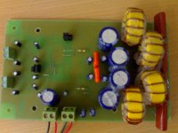
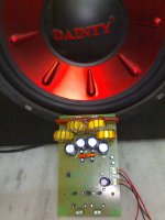
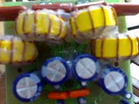
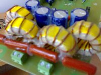
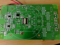
I have attached some of my PCB shots and PCB in pdf and the schematic in SLAU290. Please give me a solution.. Thank you
Regards
Udhay
My input voltage is 34V/4A
Output load - 8E/12"
PBTL config
Output inductor 14uH/5A (1mm cu wire)
Still its working but the volume is too low. No error in PCB design and assembling. What are the reasons to work like this and how can i solve this problem.
I have attached some of my PCB shots and PCB in pdf and the schematic in SLAU290. Please give me a solution.. Thank you
Regards
Udhay
Attachments

Sorry i burn two chip after this. My signal input is only 350mV peak. So i try to connect my signal directly to the chip without the op amp.... Immediately My first chip burns ...... After that i replaced with a new one. This time BTL (STEREO)cofig, no load, no input signal even no filter in output.The output ready LED glows well.The output voltage is 0.2V. I try to touch one of the input terminal of the op amp. Immediately ready LED goes OFF state. Now the output is 8V. I think my second LED also damage....
Still I have 8 chips") flame: ) and PCB'S, each 100 nos passive components for this amp design. What can i do with this chip. What is wrong with my design and why this chip is like this. Is there anybody experience with TAS5615. Please give me a solution.
flame: ) and PCB'S, each 100 nos passive components for this amp design. What can i do with this chip. What is wrong with my design and why this chip is like this. Is there anybody experience with TAS5615. Please give me a solution.
regards
udhay
...... After that i replaced with a new one. This time BTL (STEREO)cofig, no load, no input signal even no filter in output.The output ready LED glows well.The output voltage is 0.2V. I try to touch one of the input terminal of the op amp. Immediately ready LED goes OFF state. Now the output is 8V. I think my second LED also damage....Still I have 8 chips
flame: ) and PCB'S, each 100 nos passive components for this amp design. What can i do with this chip. What is wrong with my design and why this chip is like this. Is there anybody experience with TAS5615. Please give me a solution.regards
udhay
Sorry i burn two chip after this. My signal input is only 350mV peak. So i try to connect my signal directly to the chip without the op amp.... Immediately My first chip burns
Still I have 8 chips
regards
udhay
If you not mind,I think I can send one finished TAS5615 board to you ,module free,but postage will belong to you,you can try it with this board,stable working .
What is wrong with my design and why this chip is like this. Is there anybody experience with TAS5615. Please give me a solution.
regards
udhay
Where are your ceramic decoupling caps?
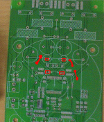
Why did not you used the ground plane? GND connections in your prototype are completely wrong, I would say... You need to get a X7R 50V SMD capacitors at least for 1uF, and connect them as shown in the attached picture. Also, there is need to place a jumpers for GND connections, as shown in the picture... Maybe it will help. Attachments
If you not mind,I think I can send one finished TAS5615 board to you ,module free,but postage will belong to you,you can try it with this board,stable working .
Wow Is it true. Can you send it for me
.. Wow it will be very useful for me. I have really lot of problem with designing a proper PCB and filter... And can you support for me to complete my full functioning amp. I contact with ti community. I follow all the routing technique and schematic of TI, But they says there are some design problems in the eve board in decoupling capacitor and output filter. But really its not mine.
The TI eve board not having an option for 2.1 and quad output then what is the meaning of evaluation board.
I am a college student and have very much interest in amplifiers design. Its my first Class D project so i really want to make it finish successfully. So if you send your board then it will be very helpful for me to correct my errors.
And i want to know your suggestion about this amp. Is it really sound good? May i use it for my subwoofer amplifier. Is there any noise in output because of 10% THD.... May i use this board design for TAS5630 is it compatible..
. Actually my plan in to design an amplifier with TAS5630. But i have only 250W woofer. Sorry i am doing this project with my pocket money only . So i will navigate to higher version in future. If you really have any idea to give me your board to me then my mailing address is here. Thanks in advance..
A.Udhaya kumar
236, 7th street Extn,.
Gandhipuram.
Coimbatore-641012.
Tamil nadu
India
regards
Udhay
Wow Is it true. Can you send it for me
I contact with ti community. I follow all the routing technique and schematic of TI, But they says there are some design problems in the eve board in decoupling capacitor and output filter. But really its not mine.
The TI eve board not having an option for 2.1 and quad output then what is the meaning of evaluation board.
I am a college student and have very much interest in amplifiers design. Its my first Class D project so i really want to make it finish successfully. So if you send your board then it will be very helpful for me to correct my errors.
And i want to know your suggestion about this amp. Is it really sound good? May i use it for my subwoofer amplifier. Is there any noise in output because of 10% THD.... May i use this board design for TAS5630 is it compatible..
If you really have any idea to give me your board to me then my mailing address is here. Thanks in advance..
A.Udhaya kumar
236, 7th street Extn,.
Gandhipuram.
Coimbatore-641012.
Tamil nadu
India
regards
Udhay
we will send it to you soon,the postage we will select arrived pay
- Status
- This old topic is closed. If you want to reopen this topic, contact a moderator using the "Report Post" button.
- Home
- Amplifiers
- Class D
- Help me my TAS5615 is working with very low volume output