Finally I red it through, and I found this is similar to a P(I)D controller with the difference, that it can be set for different Q values of output filter (while PID is optimal for only Q=~0.5).
Pro: However PID can control a high Q LC filter too, it's closed loop response is not ideal, so Charles's solution is better in this case.
A weak contra: In a ClassD amp the load impedance (at high freq) is tipically unknown, it can be much higher then nominal, so this feedback can't be exactly set also.
An other week contra: this topology is more sensitive for disturbances coming from switchings.
Combined with a more switching noise immune topology this method can be a very good solution. I have in my mind a feedback topology with improved noise immunity, I've already tested it with PID controller, it worked fine, and it can be modified easily for this high Q method. I'm going to post it here too, but currently I don't have enough time.
An other week contra: this topology is more sensitive for disturbances coming from switchings.
If that is so, it means one can get catastrophic results also during step response such as turning on the amp or removing the load might cause instability.
Though a zobel might be needed.
I think I owe you some graphics (and yes - some better qulity ones from the paper as well  ).
).
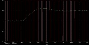
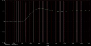
The enclosed simulations were done with the model from the paper. The output filter is 20 uH and 760 nF - resulting in a pole frequency of 40.8 kHz and a Q of 1.15 into a nominal load of 6 Ohms.
The small-signal bandwidth of the arrangement is theoretically the same as the unity-gain frequency of the loop. In the paper there is also mentioned what to do with this bandwidth and what is better be avoided.
So let's first have a look on how it behaves when used the way one shouldn't: The step input signal was directly fed to the input - withput any bandwidth restriction.
The amplitude is 50 % of the maximum input signal. Both nominal load and 1 M Ohms is shown. The latter meaning that the resulting load is actually consisting of the feedback resistor which results in a filter Q of slightly more than 400.
It doesn't fare too bad IMO given that it is used in a mode not foreseen.
).The enclosed simulations were done with the model from the paper. The output filter is 20 uH and 760 nF - resulting in a pole frequency of 40.8 kHz and a Q of 1.15 into a nominal load of 6 Ohms.
The small-signal bandwidth of the arrangement is theoretically the same as the unity-gain frequency of the loop. In the paper there is also mentioned what to do with this bandwidth and what is better be avoided.
So let's first have a look on how it behaves when used the way one shouldn't: The step input signal was directly fed to the input - withput any bandwidth restriction.
The amplitude is 50 % of the maximum input signal. Both nominal load and 1 M Ohms is shown. The latter meaning that the resulting load is actually consisting of the feedback resistor which results in a filter Q of slightly more than 400.
It doesn't fare too bad IMO given that it is used in a mode not foreseen.
Attachments
Last edited:
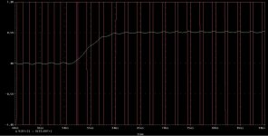
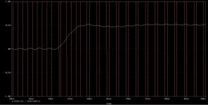
Now this is how it looks with a pre-filter. Used was Bessel 2nd order with - 3 dB cutoff frequency of 60 kHz. This might still be too high when someone intends to feed it with square-waves from function generators etc but it would be OK IMO for the use with practical audio signals. But everyone is open of course to use a lower cutoff frequency, a higher order filter or design with a higher output filter pole frequency or a lower output filter Q or ..............
The left one is again into the nominal load the right one is again with 1 M Ohm load.
Regards
Charles
The left one is again into the nominal load the right one is again with 1 M Ohm load.
Regards
Charles
Attachments
Last edited:
I think I owe you some graphics (and yes - some better qulity ones from the paper as well
It doesn't fare too bad IMO given that it is used in a mode not foreseen.
Hi Charles,
Your email address is same or its changed.
[I think my emails are seeing your spam folder]Step response is Nice as you just illustrated in the Sims. But remember i told you where the topology suffers.
, ofcourse the cure is zobel anyway.regards,
Kanwar
Hi Kanwar
I remember that you wrote that it was hard to stabilize on open loads. I also mentioned the remedy against that.
I know of someone how had built the topo. He is using it with a load that has a HUGE series inductance. It is stable without a Zobel even with this crazy load. But he will still add one for peace of mind.
Did you send me any mail recently ? The last one that I received was from the 6th of January (with the above discussion about stability).
Regards
Charles
Hi Charles,
I did sent you an email on
Yes your feedback is ultra stable when zoble is added, no doubt in that, i have checked it myself but one more thing to include was that the need of high slew rate opamp is still required. I did some tests with TL072 and LM6171, the response at HF was better with high SR opamp.
One more benefit from your topology is that, one can go for high amplitude triangle[5V pk2pk] for more linearity and less prone to switching noise without sacrificing open-loop gain as compared to direct comparator schemes.
regards,
Kanwar
I did sent you an email on
An externally hosted image should be here but it was not working when we last tested it.
28th May 2010, 03:07 PM thru this forum, you can check your inbox.
Yes your feedback is ultra stable when zoble is added, no doubt in that, i have checked it myself but one more thing to include was that the need of high slew rate opamp is still required. I did some tests with TL072 and LM6171, the response at HF was better with high SR opamp.
One more benefit from your topology is that, one can go for high amplitude triangle[5V pk2pk] for more linearity and less prone to switching noise without sacrificing open-loop gain as compared to direct comparator schemes.
regards,
Kanwar
Last edited:
I did experimented with an IRAUDAMP schematic in LTSpice. Switching frequency I used was about 500kHz (+/-50kHz). Output filter was 20uH+470nF. I have seen, if I add some disturbance to the power supply voltage, say 15kHz sinewave, it was reduced for more than 300x times (about 49-50dB) at the amp output. Lower frequency disturbances, say 100Hz, were reduced at least for 70dB, I found...
Is it possible to achieve the same results using the topology described in this thread?
Is it possible to achieve the same results using the topology described in this thread?
I did experimented with an IRAUDAMP schematic in LTSpice. Switching frequency I used was about 500kHz (+/-50kHz). Output filter was 20uH+470nF. I have seen, if I add some disturbance to the power supply voltage, say 15kHz sinewave, it was reduced for more than 300x times (about 49-50dB) at the amp output. Lower frequency disturbances, say 100Hz, were reduced at least for 70dB, I found...
Is it possible to achieve the same results using the topology described in this thread?
Hi 81Bas,
which version of IRAUDAMP?
Hi 81Bas,
which version of IRAUDAMP?
this was a IRAUDAMP1 schematic. Generally, all IRAUDAMP versions are the same, I would say. They only differ in used components, but the topology stays unchanged, as I can see. It is always a prefilter feedback with an integrator, which seem to provide such parameters.
The good PSRR is coming from the fact that it is a self-oscillating topology.
The open-loop gain is proportional to the PSU voltage. In order to compensate for it one would have to modulate the triangular carrier. Since the triangular is directly caused by the switched output voltage of the amp it is also directly modulated by the PSU fluctuations.
If you want to do a hyseresis modulator using my loop I would suggest to use only one op-amp. And maybe even make the loop an integrating one.
Regards
Charles
Hi,The good PSRR is coming from the fact that it is a self-oscillating topology.
The open-loop gain is proportional to the PSU voltage. In order to compensate for it one would have to modulate the triangular carrier. Since the triangular is directly caused by the switched output voltage of the amp it is also directly modulated by the PSU fluctuations.
If you want to do a hyseresis modulator using my loop I would suggest to use only one op-amp. And maybe even make the loop an integrating one.
Regards
Charles
this is clear, but-70dB at 100Hz with simple component-value of IRAUDAMP-1 is good too .. I think.
I saw your FB seems to work very well.
With a bit of time I could try it.
Regards
The good PSRR is coming from the fact that it is a self-oscillating topology.
I did the same experiment with UcD schematic earlier, and PSRR was only modest 25dB (what is not enough for me) at Fsw=500kHz for whole audio range, as I can remember...
Without applying various compensations, such as "PSU feed forward", the PSRR of a class D amp equals to its loop-gain, I would say. (here I mean this loop-gain: Loop gain - Wikipedia, the free encyclopedia
) The same is applicable for self-oscillating amps too, as I can see...
Last edited:
Hi,
The problem of PSRR at 100Hz is not solvable in D class. may be increased with rejection and FB filter but you get little. problem is not that the ripple (in the case TRW modulator) modulate triangular wave. ripple passes vertically from the MOSFET output.
I have experimented two transistors (Both side) of supplies drain MOSFET. transistors are inversely modulated by the ripple, but at this point is easier to create the psu with Both side regulation. (not simple but very very nice)
Regards
The problem of PSRR at 100Hz is not solvable in D class. may be increased with rejection and FB filter but you get little. problem is not that the ripple (in the case TRW modulator) modulate triangular wave. ripple passes vertically from the MOSFET output.
I have experimented two transistors (Both side) of supplies drain MOSFET. transistors are inversely modulated by the ripple, but at this point is easier to create the psu with Both side regulation.
(not simple but very very nice)Regards
Last edited:
but at this point is easier to create the psu with Both side regulation.
yes, I agree, that it is simplier for up to 1kW PSU maybe, but creating a regulated 3-4kW PSU will take much more effort, I think.
yes, I agree, that it is simplier for up to 1kW PSU maybe, but creating a regulated 3-4kW PSU will take much more effort, I think.
I think 3-4Kw has PFC and thus is already complicated.
I'm developing 2.4 kW and am using two 1.2 kW compact unit.
in the case of dual control is not easy because the two modulators must respond very quickly to requests for both real and current answer to the ripple that increases in proportion to power.
You ..can.. do..
yes, I agree, that it is simplier for up to 1kW PSU maybe, but creating a regulated 3-4kW PSU will take much more effort, I think.
Post PFC at secondary side is a good option here
It has many advantages in case of Class-D amp.
- Status
- This old topic is closed. If you want to reopen this topic, contact a moderator using the "Report Post" button.
- Home
- Amplifiers
- Class D
- Another post-filter NFB topology